Dynamic compaction commonly uses a high-energy primary pass followed by a low-energy ironing pass: the primary impacts build density at depth, while the ironing pass repairs the disturbed working surface [S6].
The method is most suitable for loose granular soils and fills, where repeated impacts can transmit stress waves through the ground and reduce void ratio; saturated clay is not an appropriate candidate [S2].
Decision rule for the two-pass sequence
The primary pass should supply the energy required for the design depth of densification, while the ironing pass should only restore surface uniformity after crater backfilling. The FHWA manual describes the sequence explicitly: “The high level energy is applied first with a heavy tamper and a higher drop” followed by “a low-level energy pass called an ironing pass” [S6].
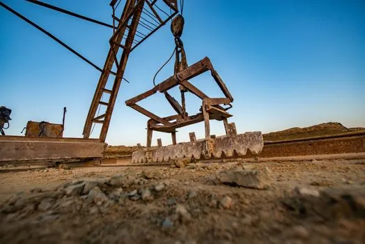
Typical tampers are 5–40 tonnes, with drop heights of 10–40 m in one implementation range [S4]. Another field description uses steel tampers of 6–30 tonnes dropped from 30–100 ft, approximately 9.1–30.5 m [S5]. These are operating ranges, not universal design values; actual energy must be matched to soil type, required depth and field response.
High-energy work can densify deposits at depths varying from 10–35 ft, or approximately 3–10.7 m, where soil conditions are suitable [S1]. The low-energy pass does not replace the primary treatment. It works on loosened material near the surface and in the backfilled craters, producing a more even platform for subsequent construction.
What each pass changes
The high-energy primary pass generates the deeper densification effect. Repeated drops transmit dynamic waves into the ground, collapse voids and rearrange granular particles. Applied energy depends on tamper mass, drop height, number of drops, grid spacing and the number of passes [S5].
The low-energy ironing pass has a narrower, surface-oriented function. After each high-energy pass, craters are leveled and compacted before further impacts [S5]. The ironing sequence addresses uneven elevations, loose crater fill and disturbed near-surface soil left by the primary impacts [S4][S6].
Selection criteria by soil and treatment objective
Dynamic compaction performs best in well-drained, high-permeability soils with low saturation. Loose sand, dredged fill and hydraulically placed fill are typical candidates, and heterogeneous fills containing large debris can also be treated because the process does not require installing rigid inclusions through the full treatment depth [S2].
Saturated granular soil may undergo temporary liquefaction and rearrange into a denser packing after pore-pressure dissipation, so rest periods may be specified between drop phases. Piezometers can be used to check dissipation [S2]. Saturated clay is unsuitable because the method does not provide the same drainage-controlled densification mechanism.
For a deep fill or natural deposit, specify the primary pass from the required improvement depth and energy demand. A separate analysis of dynamic compaction grid spacing is then needed to distribute that energy without omissions or excessive overlap. If the objective is only to densify a shallow working surface, a low-energy treatment may be sufficient, but it should not be labeled as the primary deep-densification pass.
Field execution and verification
Impacts are applied on a grid, and crater depth is a practical indicator of ground response. Grid spacing, drops per point, drop height and total passes are adjusted from the site-specific energy requirement and observed response [S5]. Crater depth can be used as an indicator of differing ground response during dynamic compaction, and craters may be backfilled and leveled after high-energy impacts.
Verification should include the treatment depth, surface elevation and geotechnical performance required by the project. Rocscience describes empirical correlations between applied energy and average SPT N or CPT qc, with outputs including estimated improvement depth, crater depth, induced settlement and peak particle velocity [S4].
Ground-vibration prediction is part of design, particularly where adjacent structures, utilities or other sensitive assets are present. The 1986 FHWA report identifies offsite ground-vibration prediction, monitoring, drop-point spacing, required unit energy and treatment-depth estimation as core design elements [S1].
Limits, failures and unsuitable applications
A low-energy pass cannot recover an underpowered primary treatment. If the primary impacts do not reach the required depth or density, adding more ironing drops mainly reworks the upper zone and consumes crane time without correcting the underlying energy deficiency [S6].
Excess primary energy is also undesirable. The process can induce ground movement, heave, settlement and vibration, while inappropriate soils may remain unstable. Impact craters can reach 6 ft or more in depth and must be backfilled [S2]. Near saturated granular ground, pore-pressure generation and temporary liquefaction require controlled sequencing and assessment of dissipation [S2].
Dynamic compaction is therefore a poor fit for saturated clay, very low-permeability ground, or sites where unacceptable vibration and settlement constraints govern. It is also not a substitute for a site-specific subsurface investigation, because the proper energy level depends on soil type, tamper mass, drop height, required depth and measured ground response [S5].
Recommended specification and acceptance
Specify the primary and ironing passes as separate work items. For the primary pass, state the tamper mass, permitted drop-height range, grid pattern, drops per point, number of passes, treatment depth and required energy basis. For the ironing pass, state that craters are backfilled and compacted before ironing and that the final pass uses lower-level energy to produce a uniform surface [S6].
Typical field tampers are about 5–6 ft in diameter, although their contact pressure and mass are tailored to the soil conditions [S5]. Do not adopt either the 5–40 tonne or 6–30 tonne range without checking equipment availability, crane capacity and the site-specific energy calculation.
Acceptance should combine production records with performance testing. Production records include tamper mass, actual drop height, drop count, grid coordinates, pass sequence and crater backfilling. Performance testing should demonstrate the specified density, settlement response and surface condition. Trial areas are especially valuable when depth estimates range toward the upper end of the reported 10–35 ft treatment capability [S1].
The correct decision is straightforward: use the high-energy primary pass to form the required deep densified zone, then use the low-energy ironing pass to close the surface after crater repair. Calibrate both passes through measured response, not through a single nominal drop height or drop count.