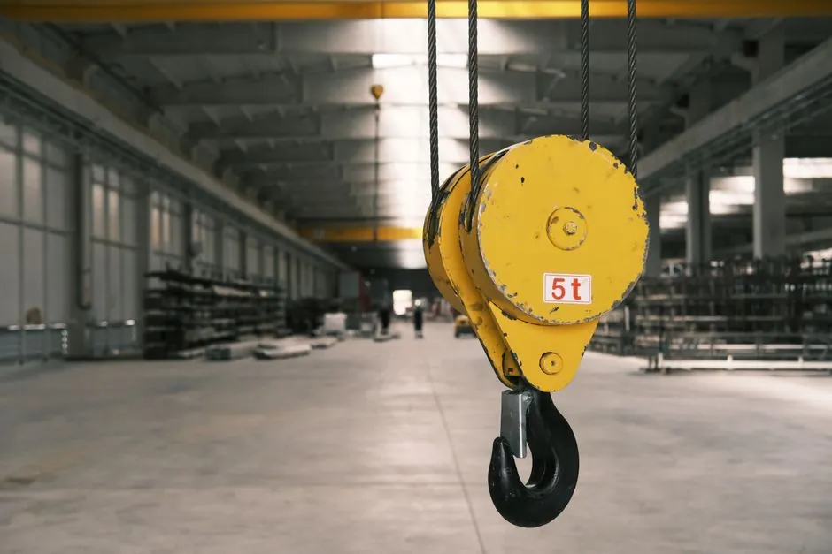
Dynamic compaction uses a heavy tamper, commonly 5–20 t, dropped from 15.4–30.8 m to densify granular fill and natural deposits [S3][S6].
Crane boom length is not the sole constraint: maximum hook height, operating radius, tamper mass, cable pull, and ground-bearing capacity must be checked together [S2][S4].
Boom Length Must Exceed the Required Drop Height
The boom must permit the tamper to be lifted above the intended release height, with the hook block and rigging included. A crane configured for 30 m hook height may not achieve a 30 m tamper drop at the working radius because the boom pivots from the crane, while the tamper hangs vertically beneath the boom tip. [S3]
Published operating ranges illustrate the distinction. A discussion of dynamic compaction describes the repeated dropping of a 5–20 t weight from heights of 60–100 ft on a grid pattern [S6], while a technical overview gives drop weights of 8–35 t and drop heights of 7–30 m [S7].
For procurement, define two quantities separately: required tamper release height above the finished or working ground surface, and minimum vertical clearance from that release point to the boom tip. Do not use nominal crane hook height as proof that the specified impact energy is available at the operating radius.
Compare the Main Crane and Drop-Height Options
Duty cycle cranes offer a practical route for repetitive drops because their winch, pull-down system, and operating cycle are designed for repeated lifting. SENNEBOGEN lists the 630 E with a maximum load capacity of up to 30 t and a maximum hook height of up to 35.5 m [S4].
These are maximum machine figures, not guaranteed working combinations. A larger boom generally increases the radius at which a given tamper remains within the crane rating, but it also raises overturning demand and may require additional outriggers or a larger base.
The comparison should therefore be made in a load chart. For each candidate crane, record the allowable tamper mass at the proposed radius, hook height at that radius, required cable pull, boom angle, machine weight, and outrigger or track loading. Select the machine that satisfies the complete combination with margin, not merely the unit with the longest published boom.
Impact Energy Is a Design Target, Not a Boom-Length Guarantee
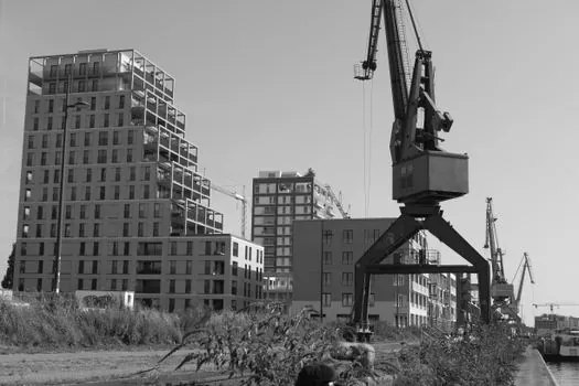
Dynamic compaction applies repeated impacts from a specified drop height. Purdue’s technical presentation describes a 5–20 t weight dropped from 60–100 ft on a grid pattern, with the method most applicable to granular fill [S6]. The Keller technical overview likewise identifies a steel drop weight as the operating element [S5].
That depth is a performance outcome, not a direct conversion from boom height. Soil type, saturation, layering, tamper geometry, drop-point spacing, number of blows, and energy transfer through the ground all affect the result [S1][S3].
A crane selected for 30 m of vertical drop must still place the tamper at the required grid locations while maintaining the specified mass and release height. If the crane reaches the target height only at a smaller radius, production may require repeated repositioning. Longer booms can improve working area and reduce machine moves, but they increase structural loading, transport constraints, and setup complexity.
Soil Suitability Determines Whether More Height Is Useful
Dynamic compaction is generally suitable for granular fill, loose sand, dredged or hydraulically placed fill, mine tailings, landfills, and collapsible deposits [S3]. Results are strongest in well-drained, high-permeability soils with low saturation, while saturated clay is generally unsuitable [S3].
This outcome must still be verified by field trials and acceptance testing.
Do not increase drop height merely because the crane can reach it. Excessive energy can create larger craters, heave, slope instability, ground-vibration impacts, and unnecessary disturbance to nearby structures. For saturated granular soil, pore-pressure generation and dissipation may require rest periods and monitoring with piezometers [S3].
Cable Pull and Repeated-Duty Performance Set the Crane Class
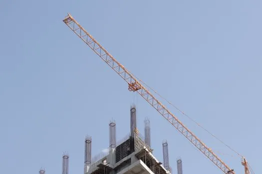
Boom height does not define drop performance without a suitable pulling system. SENNEBOGEN states that a dynamic-compaction drop plate can weigh up to 30 t and that maximum crane cable pull should be matched to the drop weight used for optimum results [S4].
Lighter tampers and smaller drops reduce the required crane size and can lower cost per unit area relative to heavier equipment [S2]. This creates a selection trade-off: a smaller crane may suit a 5–20 t tamper and moderate heights [S6], while a larger duty cycle crane may be justified where the design uses heavier weights, greater coverage per setup, or wider working radius.
Compare options on six criteria: tamper mass, required release height, working radius, maximum cable pull, machine availability, and total installed cost. A compact unit can be cheaper for a small grid, but excessive repositioning may remove that advantage. A larger machine can improve production when it combines the required height with sufficient radius and avoids repeated setup.
Field Acceptance and Constraints Govern the Final Setup
The FHWA manual provides methods for evaluating deposit suitability, estimating depth and degree of improvement, selecting drop-point spacing, estimating required unit applied energy, monitoring improvement, and predicting offsite ground vibrations [S1]. These checks are necessary because equipment selection alone cannot guarantee ground performance.
Specify an instrumented trial with at least 3 to 5 drops at representative locations and compare measured crater depth, surface response, settlement, and soil response against the design assumptions. The exact trial program should be set by the geotechnical designer, but the acceptance process must establish whether the selected tamper mass and drop height generate the required effect [S1].
Keep the allowable impact energy, drop-point spacing, pass sequence, backfilling, and rest periods in the technical specification. Also document nearby structures, buried services, vibration limits, crane base bearing pressure, and emergency procedures for suspended loads. The equipment package should include the tamper, lifting arrangement, release mechanism, base plates, survey controls, and monitoring instrumentation.
Specify the Operating Envelope Before Ordering the Crane
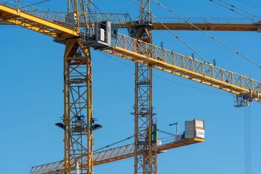
Issue the crane request as an operating envelope, not as a request for maximum hook height. State the intended tamper mass, target release height above ground, minimum working radius, required drop-point pattern, expected number of drops per shift, crane base conditions, and allowable ground-vibration limits [S1][S3].
Then request a load chart for the proposed boom configuration, including the exact working radius, tamper mass, lifting arrangement, hook height, required cable pull, and stability assumptions. Verify that the selected crane can raise the tamper cleanly to the specified release height and cycle it repeatedly without derating below the required duty.
A 30 m drop target calls for substantially more than a 30 m nominal boom dimension. Typical references place compaction drops at 15.4–30.8 m [S3], while available duty cycle cranes range from 35.5 m to 63.5 m maximum hook height across the listed 630 E through 6100 E models [S4]. The final choice must come from the rated load chart and site-specific geotechnical trial, with the dynamic compactor operating envelope established before procurement.