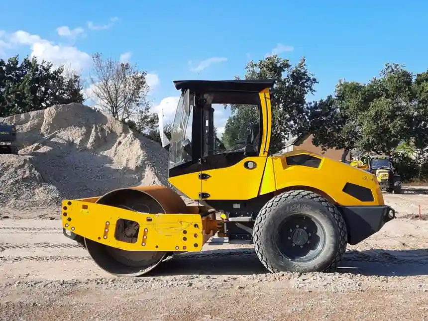
Dynamic compaction can improve granular soils and fills to depths of about 7.6 to 9.1 m, but grid spacing has no universal value because it depends on soil conditions, drop energy, drop count, and observed field response [S3][S4].
The design scope covers the treatment footprint, target depth, pounder weight and drop height, number of impacts, passes, crater handling, groundwater conditions, and verification before structural loading [S2][S3].
Depth is the starting constraint, not the grid rule
Dynamic compaction transfers high-energy impacts through the soil mass to reduce void ratio, increase density, and improve bearing and settlement performance at depth [S1][S3]. A practical design first defines the required treatment depth and then checks whether the selected impact energy can reach that depth without damaging structures or disturbing the surrounding ground.
Published practice describes typical improvement depths of about 25 to 30 ft, or approximately 7.6 to 9.1 m, with some project conditions producing less depth [S4]. That range is an applicability limit, not a guaranteed result. Soil type, fill heterogeneity, groundwater, pounder geometry, drop height, and construction control determine the actual energy field [S2][S3].
The commonly used depth relationship is D = n × W × H, where D is depth of influence, W is pounder weight in Mg, H is drop height in metres, and n is an empirical soil-dependent coefficient ranging from 0.35 to 0.6 [S4]. This is a preliminary screening tool. It does not replace trial drops, surface and subsurface response measurements, or confirmation that the target depth has been improved.
Grid spacing therefore functions as a spatial treatment parameter. If spacing is too wide, energy zones may not overlap adequately; if it is too narrow, repeated impacts may produce little additional benefit while increasing energy demand and potential ground disturbance [S3][S8].
Set grid spacing from treatment geometry and energy
Grid spacing should be developed around the required improvement footprint and target depth, using the impact pattern that produces overlapping zones of densification. Keller describes dynamic compaction as repeated heavy-weight impacts applied in a predetermined grid, while deeper applications require a deeper influence field and closer control of impact locations [S1].
Typical dynamic compaction equipment drops steel pounders of about 6 to 20 tonnes from heights of roughly 12 to 22 m [S3]. Another practice presentation identifies a broader range of 5 to 20 tons and 60 to 100 ft, equivalent to about 18 to 30 m [S4]. The weight and drop height determine the impact energy applied during dynamic compaction [S5].
Dynamic compaction applies readily calculated impact energy by repeatedly lifting and dropping a heavy weight from a height [S5]. The equation shows why spacing has a major effect on energy demand: reducing spacing raises the energy intensity per unit volume because the denominator decreases.
For level sites, the treated grid must cover the area requiring improvement plus an offset beyond the project boundary equal to the intended depth of improvement [S7]. This edge allowance protects areas near the perimeter that would otherwise receive less treatment because the influence field falls away beyond the outermost impact locations.
Compare spacing choices against four decision criteria

A wider grid reduces the number of impact points and can improve production rate, but it risks incomplete overlap, especially where soil density varies or the required depth approaches the practical limit [S3]. A narrower grid increases overlap and treatment uniformity, but it also raises applied energy, crane time, vibration exposure, and cost [S4][S8].
The comparison must include four criteria rather than spacing alone: target depth, soil response, energy demand, and boundary sensitivity. The dynamic compactor is the execution system, not a substitute for geotechnical design, because the same weight and drop height can produce different soil responses under different boundary and groundwater conditions [S2][S4].
Tailor spacing to soil and groundwater conditions
Dynamic compaction is primarily applicable to granular soils, and it has also been successful in improving urban fill materials, mine spoils, liquefiable sands, and collapsible soils [S3][S4]. Grid spacing must reflect that soil variability rather than apply a single pattern across a mixed site.
A shallow groundwater table can absorb impact energy at the soil-water interface while generating pore pressure, which may require additional working time and a modified sequence [S4].
Pounder contact pressure also affects treatment behaviour. Higher contact pressure can assist penetration, while lower pressure can promote more uniform surface lowering, so spacing and tamper selection should be reviewed as one system.
Field performance must override nominal assumptions. If fewer than five drops are needed at a location, the grid may be too tight; if the impact crater becomes too deep, multiple passes may be required [S8]. These observations indicate when to modify spacing, passes, or both.
Use trial drops to calibrate the working grid
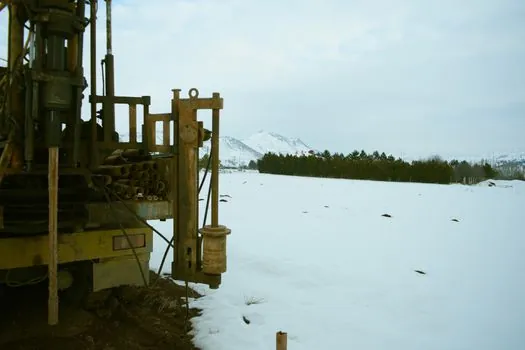
Dynamic compaction design is not complete before field calibration. The grid spacing, drops per impact point, drop height, and number of passes depend on site-specific soil conditions and observed performance [S3]. Trial impacts should be placed away from sensitive assets where practical, then evaluated through crater geometry, surface response, settlement, and geotechnical testing.
The trial sequence should test the intended pounder weight, drop height, impact count, and spacing. If the soil response is weaker or more variable than assumed, the contractor can reduce spacing or increase energy per location. If craters become excessively deep, the program may need flatter tamping faces, additional passes, or crater backfill and reworking before the next phase [S8].
Verification should extend to the depth that matters for the project, not only the surface. A treatment that raises bearing capacity at shallow depth but leaves variable conditions below the foundation zone has not demonstrated the required ground improvement. The diaphragm wall grab, for example, is not part of the dynamic compaction grid design, but nearby excavation equipment and retained structures may impose vibration and displacement constraints that influence permissible execution.
Dynamic compaction also generates high vibration levels and is less suitable near sensitive structures within roughly 50 ft, or about 15 m, without careful project-specific assessment [S4]. Grid spacing cannot solve an unacceptable vibration setting; reducing impact energy, changing the sequence, using a lower-vibration system, or relocating the treatment may be required.
Define the acceptance test before full execution
Acceptance criteria should state the required improvement depth, target density or relative compaction where appropriate, bearing performance, settlement limits, permissible variability, and the method and depth of verification. Dynamic compaction is used to increase bearing capacity and reduce total and differential settlement, often allowing conventional shallow footings or slabs-on-grade [S3][S5].
Reported dynamic compaction results can provide bearing capacity of typically 100 to 150 kPa, equivalent to 2,000 to 3,000 psf, in suitable applications [S5]. This is an indicative performance range, not a design guarantee. Acceptance values must match the foundation loading, soil profile, seismic requirement, and construction sequence.
Recommendations for selecting impact energy at a specified fill depth are covered in dynamic compaction energy selection for a 6 m fill. Energy selection and grid spacing should be developed together because applied energy per unit volume depends on both the energy per impact and the square of grid spacing [S4].
The final issued work plan should include the treatment boundary, offset, grid coordinates, pounder geometry, weight, drop height, drops per point, passes, crater-formation procedure, groundwater controls, vibration controls, trial-drop results, and acceptance testing. That package allows a field team to distinguish a genuine design change from normal variation in soil response.
Track two signals during execution: the ratio of field-adjusted spacing to the preliminary design spacing, and the percentage of test locations meeting the specified depth and acceptance criteria. A reduction in spacing that materially improves depth performance indicates an overlap or energy-density issue, while a stable grid with acceptable test results supports completion without unnecessary additional impacts.