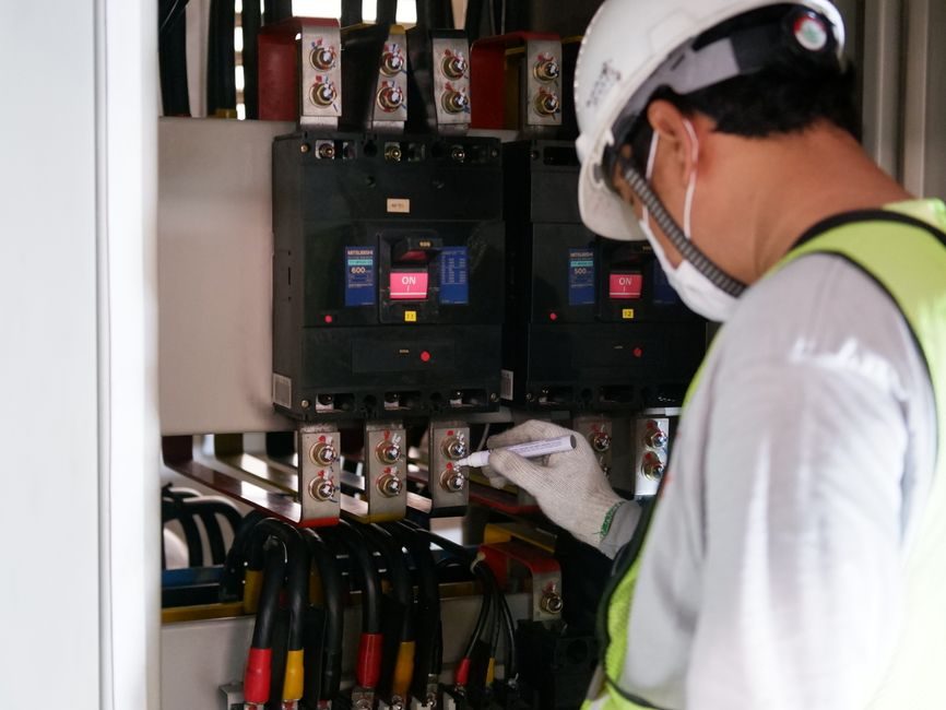
Field-grade earth ground resistance testers shipped in 2025-2026 cover 0.001Ω resolution to 3000Ω full-scale, with 0-600V AC earth-voltage readout and 400-500 group onboard memory on mid-range units [S1][S2][S7]. Selecting among them is fundamentally a question of test method, electrode topology, and whether the bond under test can be disconnected from the running plant.
Three physical test topologies dominate procurement: 3-pole / 4-pole fall-of-potential kits with auxiliary ground stakes, 2-pole simplified units for bonded-against-a-known-reference measurements, and clamp-on non-contact meters for live systems. The earth ground tester method chosen dictates the staking crew, lead lengths, and the minimum reading you can trust in the field.
Test Method Determines the Stakeless vs Fall-of-Potential Split
Clamp-on ground resistance testers work by injecting a known voltage on the clamp jaw and sensing the return current through the loop formed by the grounding electrode, the soil, and any parallel return paths, so they need a multi-rod or bonded grid to read a meaningful number and they will not resolve a single isolated rod [S3][S4]. Fall-of-potential 3-pole and 4-pole testers inject current through one auxiliary stake and measure voltage drop against a second potential stake, which is the method specified by the dominant international practice (IEEE 81) and the one every utility substation audit still asks for.
Typical commercial 4-wire kits sold in 2025-2026 span roughly 0.01Ω to 2000Ω across three manual ranges, with the Extech 382152 / 382252 family explicitly advertised in that window [S3]. Entry-level digital 2-pole units stretch the upper end to 3000Ω at 0.01Ω resolution with 500-group memory, which fits residential and light-commercial bonding checks where an independent reference electrode is already bonded to the system [S7].
Range, Resolution, and Earth-Voltage Readout
Resolution and full-scale range must both be checked at the procurement stage, because vendors quote the smaller number on the datasheet headline. A 0.001Ω resolution unit (clamp-type) is meaningless at the 2000Ω end of the IEC 62561-series lightning-protection acceptance range, while a 3000Ω full-scale 0.01Ω unit cannot catch a sub-1Ω substation ground that the utility inspector will flag [S1][S7]. Mid-range 2025 production testers commonly offer ground resistance 0.01Ω-2000Ω plus AC 0-600V earth-voltage on a separate channel, with a 20 mA max short-circuit test current to keep the injected signal below personnel-protection thresholds [S2].
Data-hold, auto-range, and onboard memory (400 or 500 groups) are now standard on most non-clamp units in the US$345-US$742 retail band, which removes the clipboard-and-pen error path on long substation sweeps [S2][S5][S7]. For sites where the test report has to be uploaded to a CMMS, look for USB or Bluetooth output explicitly; many of the same 2025-vintage meters omit it and force a manual transcription step.
Clamp-On Units: Live Systems, But With a Hidden Assumption
Clamp-on ground testers (e.g. the ETCR2000C+, Extech 382357 / 382356) are the only practical option when the grounding conductor cannot be isolated from a live plant, because they inject and sense through a single jaw and do not require auxiliary stakes [S3][S4]. The published 0.001Ω resolution figure on the ETCR2000C+ (US$438 listing, 2025-02) refers to the lower limit of the dynamic range, not measurement accuracy; the method requires a parallel return path and will under-read an isolated single rod by an order of magnitude or more [S1][S4].
For routine inspection of telecom towers, data-center PDU grounds, and streetlight circuits where multiple down-conductors share a grid, the clamp-on method is roughly 5-10x faster than a 3-pole sweep because no spikes are driven and no leads are unreeled. Where the practice (NFPA 780, IEC 62305) still requires fall-of-potential validation at commissioning, the clamp reading is a screening tool only and must be backed by a staked measurement on a representative sample.
Soil Resistivity and Wenner 4-Pole Surveys
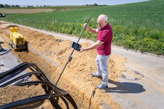
For grounding-system design rather than periodic verification, a soil resistivity tester is the correct instrument: a Wenner 4-pole array injects current through outer stakes and senses voltage on inner stakes to back-calculate ρ in Ω·m [S5]. Commercial 2025 soil resistivity meters cover 0-30 kΩ resistance and 0-9000 kΩ·m apparent resistivity, which spans everything from moist alluvial clay (~50 Ω·m) to dry rocky till (>5000 Ω·m) without re-ranging in the field [S5].
Station-design engineers should record resistivity at multiple stake spacings (typically 2 m, 5 m, 15 m, 30 m) so the layered-soil model can be fitted, not just a single averaged number; this is where insulation resistance testers and ground testers are routinely confused by junior buyers even though the test signals and electrode geometries are completely different.
Selection Criteria Mapped Against Real Use Cases
Four decision criteria separate the three main options for a working engineer: (1) whether the system can be de-energized, (2) whether a parallel return path exists for clamp-on methods, (3) the minimum reading the inspector will accept (typically 0.1Ω for substations, 5-25Ω for telecom and lightning protection), and (4) the resistance-to-earth acceptance threshold set by the relevant practice. A 3- or 4-pole fall-of-potential kit is the only credible answer for substations, large wind turbines, and HV yards; a 2-pole simplified tester is the cheapest option for residential and small-commercial bonding against a water-pipe or building steel reference; a clamp-on meter is the only practical answer for live PDU/cabinet grounds and streetlight grids [S2][S3][S4][S6][S7].
A representative shortlist, priced roughly at 2025-2026 retail, looks like this: clamp-on ETCR2000C+ at US$438 (0.001Ω resolution, alarm function, for live systems) [S4]; entry-level 2-pole digital kit at US$345 (0.001Ω, for residential) [S1]; mid-range 0-2000Ω 2/3-wire meter at US$526 with 0-600V AC earth-voltage and 400-set memory (for light-commercial) [S2]; CNYST 0.01-3000Ω with 500-set memory (for facility maintenance) [S7]; and a dedicated 0-9000 kΩ·m soil resistivity tester at US$742 (for greenfield grounding design) [S5]. Fluke's published guidance explicitly references the International Electrical Testing Association (NETA) interval of ground-electrode testing every three years as the maintenance trigger for the verification-tier picks [S6].
Who Should NOT Buy the Clamp-On Mainstream Pick
A clamp-on ground tester is the wrong primary tool for any commissioning test on a new substation grid, a wind-turbine foundation, or a lightning-protection down-conductor on an isolated building, because the loop assumption fails and the reading collapses toward zero. Buyers who specify the ETCR2000C+ or a generic 0.001Ω clamp unit as a "single instrument for everything" will pass clamp-based screening and then fail the fall-of-potential witness test the utility engineer actually runs. The clamp meter vs earth ground tester decision is not a brand preference; it is a method-of-test preference, and the two are complementary rather than interchangeable. [S1]
For HV and substation work, also avoid any 2-wire-only unit regardless of resolution, because 2-wire measurements fold the stake resistance and the lead resistance into the reading and will systematically over-read by 1-10Ω on low-impedance grounds [S2][S7]. In practice, 2-wire units belong on the residential electrician's truck, not on the decade resistance box calibration bench or the substation commissioning cart.
Standards, Intervals, and Sourcing Notes
Three-year ground-electrode test intervals are the published NETA maintenance trigger, and the IEEE 81 fall-of-potential method plus Wenner 4-pole soil-resistivity array are the de-facto field procedures across North American utility practice; Fluke's earth-ground product page states the three-year interval and the need for a safe earth path under lightning or utility overvoltage explicitly [S6]. IEC 62305-series lightning protection and NFPA 780 set the typically ≤10Ω (Class I-II) and ≤25Ω acceptance thresholds for down-conductors that the procurement spec should call out, not the instrument vendor.
Sourcing in mid-2026 is dominated by Chinese OEM brands (ETCR, CNYST, Deree) on global marketplaces, with US-list pricing between roughly US$345 for a 0.001Ω clamp unit and US$742 for a 0-9000 kΩ·m soil resistivity meter [S1][S4][S5][S7][S8]. A reasonable spec floor for a new 2026-vintage facility-maintenance kit is 0.01Ω resolution, 0-2000Ω range, 0-600V AC earth-voltage channel, ≥400-set memory, and a 3-pole/4-pole mode — anything less and the unit will be inadequate for the first substation audit. For a deeper cross-instrument comparison, see also the insulation resistance tester vs power quality analyzer map, since both instruments are often co-specified on the same commissioning datasheet.