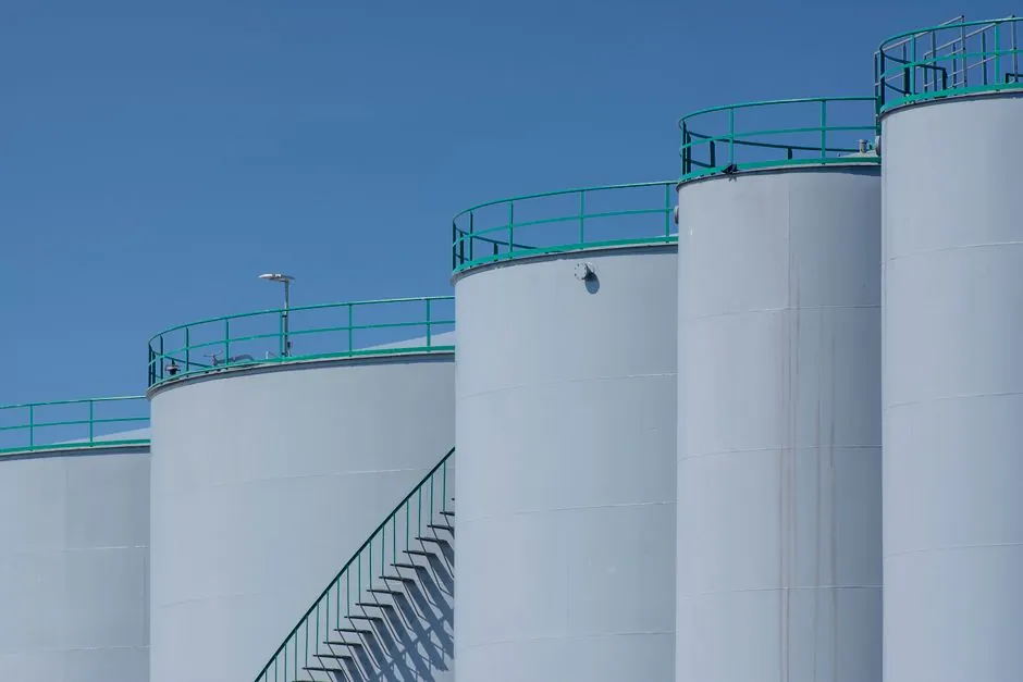
Hydrogen electrolyzer balance of plant converts AC electricity into controlled DC and removes entrained water or electrolyte from hydrogen and oxygen before delivery, storage, or further purification.
The equipment scope includes transformers, rectifiers, DM/DI water treatment, pumps, electrolyte circulation where applicable, gas-liquid separators, dryers, analysers, and safety monitoring.
Rectifier and power-system duties
Electrolyzer stacks require controlled direct-current power, so the power conversion train normally includes a transformer, rectifier, controls, and the DC distribution equipment needed to match stack voltage and current [S1]. A rectifier converts the AC electrical supply into DC, while the wider power system also supports auxiliary loads [S1][S2]. This is not a discretionary accessory: inadequate power conversion or control directly limits the stack operating envelope and the repeatability of gas production.
The stack manufacturer defines the electrical operating range. Research on alkaline electrolysis identifies current densities of 0.5–1 A/cm² at the electrode and notes that most supporting equipment operates across 5–90% of nominal capacity, with power management required to maintain the specified voltage over that range [S3]. PEM and AEM architectures differ from alkaline systems, so the rectifier package should be selected against the selected stack rather than copied from a generic hydrogen project [S1][S4].
Gas-liquid separation and product routing
Gas leaving an electrolyzer can carry water or electrolyte droplets, which is why the BoP includes gas-liquid separators, demisters, and return circuits to separate bulk liquid and entrained droplets [S1]. Hydrogen and oxygen remain in separate streams, with level and pressure monitoring matched to each process loop [S1]. The separator is therefore both a product-conditioning device and a containment boundary that reduces liquid carryover into downstream gas-handling equipment.
The separator does not complete gas purification. It removes bulk liquid and entrained droplets, but downstream drying is still required for moisture control, and trace oxygen in hydrogen requires a separate treatment step where the product specification demands it [S1]. A downstream gas-liquid separator is not interchangeable with a hydrogen purification train, since the latter addresses moisture, residual oxygen, and other specified contaminants.
Alkaline electrolysers use an alkaline electrolyte, commonly potassium hydroxide, and their balance of plant includes an electrolyte tank and pumps [S1][S2]. Seals and glands must therefore be suitable for high oxygen concentrations [S3]. A coalescing filter may be used within a liquid-treatment arrangement, but the separator and demister remain the primary bulk phase-removal elements in the gas path [S1][S3].
Water and electrolyte preparation
Network water must be demineralised before use in either PEM or alkaline electrolysis, with reverse osmosis and ion-exchange resin identified as suitable treatment stages [S3]. Network-supplied water must be demineralised for use in either PEM or alkaline electrolysers, with feedwater quality and flow specified around the selected equipment [S1][S3]. Source-water mineral composition should be checked for seasonal variation because the required treatment depends on the actual incoming water [S3].
Alkaline systems commonly circulate potassium hydroxide dissolved in treated water, and the supporting package can include preparation and storage tanks, circulation pumps, filters, and heat exchangers [S1]. Some AEM designs use a dilute circulating alkaline solution, but that does not justify copying the KOH circuit from a conventional alkaline plant because concentration, preparation, and circulation arrangement depend on the manufacturer’s design [S1]. PEM systems do not use a lye circulation circuit [S1].
The broader treatment package can include treated-water storage, transfer pumps, conductivity monitoring, and distribution piping [S1]. Where applicable, a basket strainer can protect downstream pumps or heat exchangers from particulate, but the water-quality requirement still applies to the protected equipment rather than to the strainer itself [S1][S3].
Rectifier, separator, and dryer comparison
A cyclone separator offers a different separation mechanism from a vessel-based gas-liquid separator, while a dryer addresses moisture after bulk liquid removal. The selection should be made against phase loading, gas composition, pressure, flow, and the required product specification rather than by equipment size alone. [S1]
Cooling and condensate separation remove bulk moisture after that reaction, and adsorption drying removes remaining water vapour [S1]. PSA or TSA selection must account for inlet contaminants, flow, pressure, dew point, hydrogen recovery, and supply continuity [S1].
Purity, pressure, and failure controls
BoP design must satisfy the electrolyzer manufacturer’s water, electrical, and gas specifications at the same time; failures in supporting equipment can degrade the membrane or cause product gas to miss its specification [S3]. Continuous monitoring of pressure, level, moisture, and residual oxygen gives operators a check on the gas path rather than relying on the stack alone [S1][S2]. For PEM systems, recirculating anode water is specified at 60–80°C, and the circuit requires controls for metal-ion contamination from bipolar plates, diffusers, and stainless-steel components [S3].
Pressure is a design input, not an automatic BoP output. A published medium-size PEM electrolyzer arrangement demonstrated hydrogen delivery up to 40 bar without a compressor [S6]. That result belongs to that specific design, so it cannot be transferred automatically to every PEM stack or treated as a universal operating limit [S6]. For a separate hydrogen buffer system, the relevant engineering discussion is hydrogen compressor lead times, since storage and compression scope can change the delivery architecture.
Application fit and operating limits
PEM electrolysers suit variable renewable input because they respond quickly to power fluctuations, but they use platinum-group materials; alkaline electrolysers use KOH or NaOH and operate at 60–80°C; solid oxide electrolysers operate at 600–1000°C and use waste heat; and AEM systems have a different electrolyte and BoP configuration [S4]. This comparison matters because the power conversion, liquid circulation, materials, and gas-separation duties must follow the electrolysis technology.
A hydrogen plant is a better fit for an operator willing to integrate controlled rectifier output, DM/DI water, separated H₂ and O₂ circuits, purification, analysers, and shutdown instrumentation. It is not a better fit for a simple skid that omits water treatment, drainable liquid paths, gas detection, pressure monitoring, or product-gas analysis [S1][S2]. The BoP boundary should be fixed before procurement because some systems are built into the manufacturer’s package while others arrive as separate skids or site infrastructure [S1].
The next engineering node is to freeze the stack-specific DC operating envelope, feedwater conductivity and flow, separator pressure and liquid-load cases, and downstream hydrogen purity and dew-point targets. Those four documents determine the rectifier rating, separator geometry, treatment train, and test plan [S1][S3].