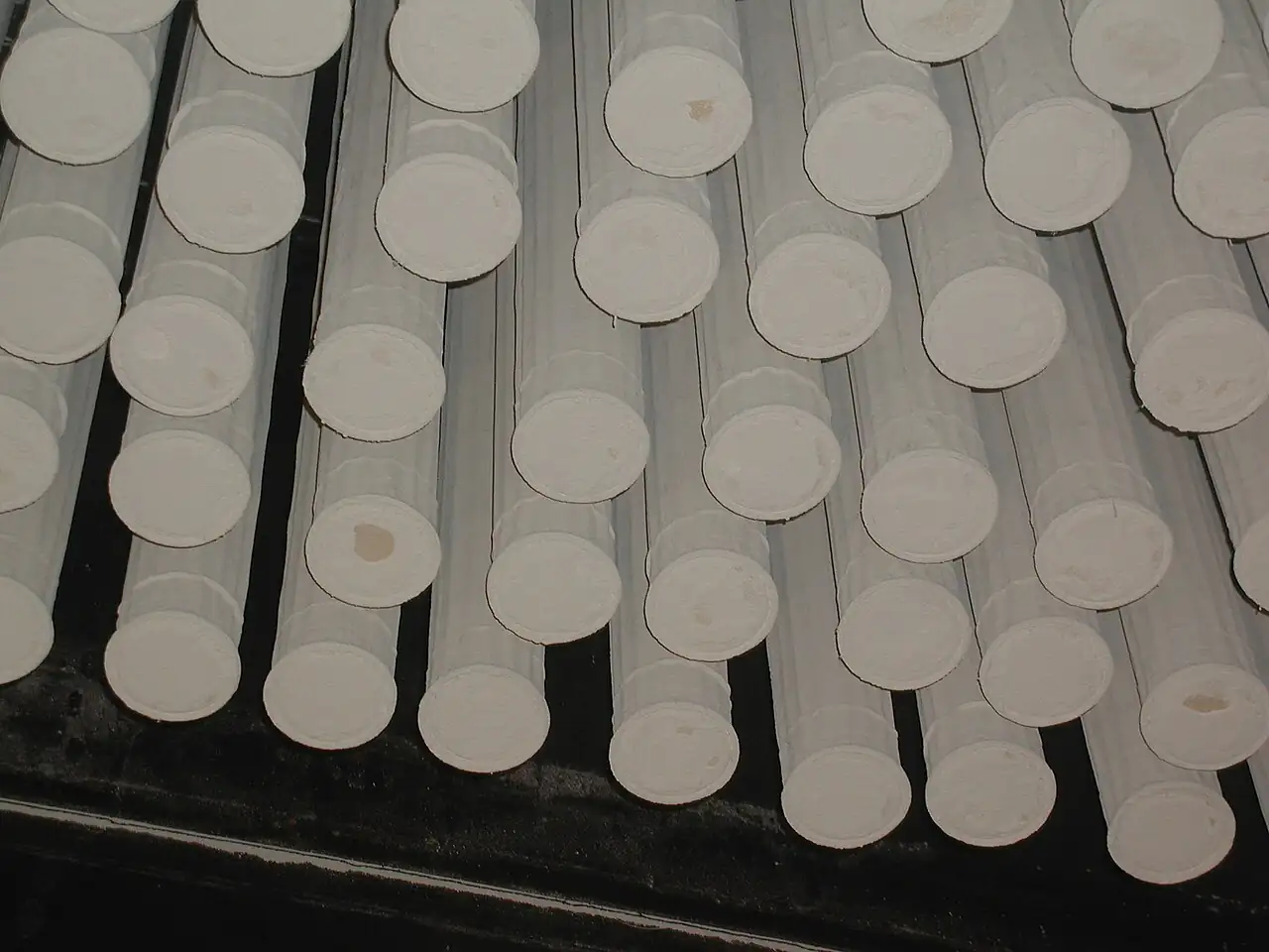
A coalescing filter is a pressure vessel fitted with a depth media element whose job is to intercept submicron oil and water aerosols carried in compressed air and gas, grow them into droplets heavy enough to fall, and route those droplets to a drain before they can travel downstream. The element is a mat of borosilicate glass microfiber, wrapped in layers or pleated into a high area pack, and the vessel beneath it carries a manual, float, or electronic drain. Element grades map directly onto the ISO 8573-1 air quality classes for oil aerosol content: general purpose elements leave 0.5 to 1 mg/m3 of oil in the air, high efficiency grades leave 0.01 mg/m3. Housings run from cast aluminium at a 16 bar rating to carbon and stainless steel above that, with ports from small G threads to flanged DN sizes. Clean pressure drop is 0.05 to 0.15 bar, and the element is changed at a terminal differential of 0.4 to 0.7 bar.
Procurement engineers meet this hardware on instrument and plant air stations downstream of an oil injected screw compressor, ahead of desiccant dryers whose adsorbent is destroyed by oil, on biogas and fuel gas cleanup skids, on lube oil mist capture, and in the sample conditioning path that protects analyzers. The decision this page settles is narrow and practical: which element grade the ISO 8573-1 target actually requires, which housing material and drain the service demands, where in the train the filter belongs, and what change interval the pressure drop economics support. The answer lands as an RFQ line set: flow and reference pressure, target class and remaining oil, inlet temperature, drain type, ports, and monitoring. Every chapter below feeds that line set so the air quality is bought, not hoped for.
This page treats the coalescing filter as a purchasing object: what the depth media physically does to a 0.1 um aerosol, how ISO 8573-1 classes translate into element grades and remaining oil figures, how pressure drop and drain choices decide energy cost and re-entrainment risk, and how grade, housing, drain, and train position combine into a defensible RFQ. It is written for engineers who issue purchase specifications for compressed air and gas quality, not for readers who want a brochure summary.
Chapter 1 / 06
What a Coalescing Filter Is and What Is Being Decided
The coalescer exists because of what an oil injected screw compressor leaves behind. The machine separates most of its lubricant mechanically, but downstream of the aftercooler and the internal separator the air still carries a few milligrams per cubic meter of oil aerosol in the 0.01 to 1 um size band, mixed with condensed water aerosol from the cooling that follows compression. Those droplets are far too fine to settle in a drip leg and too small for a screen. A coalescing filter is the depth media element that intercepts them inside a fiber matrix, merges them into droplets a hundred times heavier, and lets them drain away. What it does not do is equally important: it passes vapor. Water vapor is removed to a dew point by refrigeration or adsorption in an air dryer, and oil vapor at the ppm level needs an activated carbon stage downstream. A buyer who expects the coalescer to fix a dew point problem has bought the wrong unit for the wrong contaminant.
What is actually being decided in this purchase is a set of six linked choices. First the grade: general purpose elements with 0.5 to 1 mg/m3 remaining oil suit plant air, while high efficiency grades at 0.01 mg/m3 are what an ISO 8573-1 Class 1 oil target requires. Second the housing: cast aluminium at a 16 bar class is the commodity answer, with carbon and stainless steel above it for pressure, chemistry, or gas duty. Third the ports, from G threads to flanged DN connections, set by the station piping. Fourth the drain, because a coalescer that cannot discharge its liquid re-entrains it. Fifth the position in the train, which the dryer maker and the contaminant physics fix together. Sixth the change interval, which is a pressure drop decision with a real energy cost attached, not a calendar habit. Each choice is a line in the RFQ, and each is treated in a chapter below.
The train position deserves the first paragraph of engineering honesty, because it is the choice most often bought wrong. The standard sequence is compressor, aftercooler, coalescing filter, then dryer, in that order, unless the dryer maker says otherwise. The aftercooler condenses bulk water so the coalescer sees droplets rather than vapor it cannot catch. The coalescer then protects the dryer: oil poisons desiccant beds permanently, and a bed that has taken oil dew points badly for the rest of its life. Downstream of an adsorption dryer a dry particulate element catches desiccant dust. At the point of use, an FRL unit integrates a small filter, a pressure reducing valve, and a lubricator for tool air, and it is no substitute for the main station coalescer upstream. Instrument air specifications in the ISA 7.0.01 family commonly demand a dew point near minus 40 deg C and low oil content together, which is why the air dryer and the coalescer are always purchased as a pair.
Four standards organize the datasheet. ISO 8573-1 defines the air quality classes by contaminant, and its oil aerosol table, 0.01 mg/m3 for Class 1, 0.1 for Class 2, 1 for Class 3, 5 for Class 4, is the vocabulary of every grade chart in every catalog. ISO 8573-2 fixes how oil aerosol content is actually measured, the sampling hardware and procedure behind any honest remaining oil claim. ISO 8573-4 does the same for particulate content, and ISO 7183 covers the air dryers that handle the vapor side. A datasheet that quotes a remaining oil figure without an ISO 8573-1 class or a test basis is quoting a hope. The verification chain matters at purchase: the class is the requirement, the grade is the offer, and an ISO 8573-2 style measurement, on site with indicator tubes or in a lab, is the proof.
The RFQ should also name the neighboring hardware honestly so one supplier can check the whole station. Upstream during commissioning, a Y strainer on the main catches weld bead and pipe scale that would otherwise load the element in its first week. Condensate drainage from the aftercooler and the filter sump belongs to a properly trapped drain system, not a hole in the bottom of a line. Downstream, the air dryer completes the quality chain, and a dew point transmitter on the dryer outlet is how the plant watches the vapor half of the specification. Stating the station rather than the vessel lets the quotation come back as a matched set instead of four unrelated part numbers that meet for the first time on the skid.
Chapter 2 / 06
How Coalescing Media Capture and Release Aerosols
The element is a graded density mat of borosilicate glass microfiber. Fiber diameters are in the submicron range themselves, and the packing density is arranged so that the mixture of fiber and air presents a tortuous path with a large share of empty space, typically well above 90 percent void, so pressure drop stays low while the probability of a droplet striking a fiber stays high. Depending on the maker the element flows from inside to outside or the reverse, and the direction is marked on the end cap for a reason: the media grading, support layers, and drainage surface are built for one direction, and an element installed backwards captures poorly and sheds droplets into the clean side.
Capture works by three mechanisms, and droplet size decides which one dominates. Below roughly 0.1 um, aerosol particles move by Brownian diffusion, wandering across streamlines and landing on fibers almost regardless of bulk velocity. Between about 0.1 and 1 um, direct interception dominates: a droplet following a streamline passes close enough that its own radius carries it onto a fiber. Above about 1 um, inertial impaction takes over, with droplets too heavy to follow the streamline around a fiber and striking it directly. The practical consequence is the efficiency curve's weakest point near 0.1 to 0.3 um, the most penetrating size band, and honest grade charts quote efficiency at that challenge, which is why the remaining oil figures in catalogs are meaningful: they are measured where the media is worst, per the sampling logic of ISO 8573-2.
Coalescence itself is what happens after capture. A droplet that lands on a fiber wets the glass surface, joins the film already there, and grows by the arrival of the next droplets and the next. Surface tension and the airflow drag the film along and through the mat, and droplets leave the downstream face one to two orders of magnitude larger than they arrived, large enough that gravity takes over in the housing sump below. The physics sets two purchase-relevant limits. Face velocity must stay in the maker's band: too fast and the droplets re-entrain as a fine mist worse than the inlet load, too slow and the vessel is oversized capital doing nothing. And the housing sump must actually hold liquid between drain cycles, because a sump kept full by a failed drain puts free liquid directly back into the airstream.
The drain is half the machine. A manual petcock is a maintenance promise nobody keeps, and plants that fit them re-entrain oil within months. A float drain opens when liquid lifts the float, wasting a little air each cycle but asking nothing of the operator. An electronic zero loss drain uses a timed solenoid valve, often with a capacitance or resistive level sensor, to discharge liquid without bleeding compressed air, and its alarm contact belongs in the control room. On refrigerated dryer outlets and aftercoolers, where condensate is continuous and oily, the zero loss type pays for itself in compressed air energy quickly. The drain line itself must fall freely to a treated condensate point, because oil bearing condensate is a waste stream, not a floor drain guest.
Pressure drop is where the money lives. A clean element costs 0.05 to 0.15 bar across the vessel, and as aerosol and the occasional coarse dirt load the mat, the differential climbs. The economic change point is 0.4 to 0.7 bar, and the reason is compressor energy: as a family figure, every 1 bar of avoidable pressure drop at the machines costs on the order of 7 percent of compressor input power, so a terminal differential of 0.7 bar on a large station is a real line on the energy bill. That is why the RFQ should demand a differential gauge or transmitter on every housing and treat the change interval as an output of a trend, not a guess. Capacity correction matters in the same paragraph: catalog flow ratings are quoted at a reference pressure of 7 bar, and an element at 10 bar carries proportionally more air, while the same element moved to a 3 bar network is a much smaller filter than its label.
Temperature closes the physics. Standard coalescing media and elastomer end cap seals are built for compressed air in roughly the 1.5 to 66 deg C band at the element face, with high temperature versions extending to about 80 deg C and beyond with fluorocarbon sealants and treated media. Above the media's limit the binder and the seal age in weeks, oil vapor fraction rises, and the grade quietly stops meeting its remaining oil claim. Hot discharge air taken straight off a screw compressor before the aftercooler is the classic way to kill a coalescer, and it is one more reason the train order in chapter 1 is not negotiable.
Chapter 3 / 06
Types, Construction, and Duty Boundaries
Catalogs divide the family by grade before anything else. A general purpose coalescer, the workhorse after the aftercooler, leaves 0.5 to 1 mg/m3 of remaining oil, which supports ISO 8573-1 Class 3 air for general plant use. A high efficiency oil removal grade, the families exemplified by the Parker OIL-X line and the Donaldson P-SMF and V series elements cited in the sources below, leaves 0.01 mg/m3, the Class 1 figure, and is what instrument air, paint spraying, and desiccant dryer protection call for. Above those sit the high flow pleated constructions, the Donaldson UltraPleat M and S pattern, which put pleated media into large flow service with a lower clean pressure drop and fewer parallel housings. A dry particulate grade, mechanically a dust element rather than a coalescer, completes the train after an adsorption dryer to catch desiccant dust.
Element construction separates into wrapped and pleated architectures. Wrapped elements spiral the microfiber mat with drainage layers into a cylinder, are economical, and dominate the small and mid sizes. Pleated elements fold the media into a high area pack, trading some depth for surface, which lowers face velocity and clean differential and suits high flow. Both carry support cages inside and out, bonded end caps, and a sealinggasket, nitrile as standard and fluorocarbon for temperature or chemical duty. The gasket is a precision part, not a consumable afterthought, and the most common assembly error in the field, an element seated on a damaged gasket, bypasses the entire media pack silently.
Housings divide by material and rating. Cast aluminium modular housings, tie-rod assembled with interchangeable heads and bowls, carry the 16 bar class and dominate the machine mounted and station duty from small port sizes through the mid flow range. Carbon steel housings, welded and painted or coated, take higher pressures and outdoor gas skid duty. Stainless steel serves food, pharmaceutical, and corrosive gas service where aluminium condensate corrosion or product compatibility rules the ordinary materials out. Ports scale from G1/4 to G2 threaded connections at the small end to flanged DN 50 to DN 300 at the large end, and the RFQ should state the standard, BSPP or NPT or flange drilling, at order time because the element does not care but the erection crew does, and because a pipe fitting ordered to the wrong thread standard is scrap on the dock. Housing options that matter are the differential gauge or transmitter port, a bypass valve that cracks at a set differential to protect continuity at the cost of quality, and manifold kits that let several housings share one station.
Drain options repeat the chapter 2 physics in hardware. The internal float drain is the commodity fit for intermittent condensate; the electronic zero loss drain, built around a solenoid valve and a level or timer control, is the reliable fit for continuous oily condensate and pays back in air that is no longer vented. On gas duty, where the condensate can be flammable or the housing sits in a classified area, the drain and its electrical enclosure must carry the appropriate certification, and this is a line item to state explicitly on biogas and fuel gas skids.
Duty boundaries keep the purchase honest. The coalescer is not a bulk liquid separator: free water and oil slugs belong to a cyclone separator or a generous drip leg upstream. It is not a dust collector either: heavy particulate loading blinds the mat and belongs to washable prefilters, and the dust and bulk liquid family duty is the bag filter's territory, which is a different machine with different physics. It removes no vapor: the air dryer owns water vapor and the dew point, activated carbon owns oil vapor. It respects a temperature ceiling near 66 to 80 deg C by media family. And on gases other than air, from biogas with its hydrogen sulfide trace to fuel gas and cover gas, the housing material, elastomers, and drain certification all follow the gas analysis, and a catalogue aluminium housing quoted without that review is a corrosion incident on a schedule.
The table below compresses the grade decision into the form a specifier can carry into a review meeting.
Grade family
Media and remaining oil
Clean pressure drop
Typical placement
General purpose coalescer
Wrapped microfiber, 0.5 to 1 mg/m3
0.05 to 0.15 bar
After aftercooler, plant air networks
High efficiency oil removal
Wrapped or pleated fine fiber, 0.01 mg/m3
0.10 to 0.20 bar
Instrument air, desiccant dryer protection, Class 1 targets
High flow pleated
Pleated depth pack, 0.01 mg/m3 class
0.05 to 0.10 bar
Large single line flows, fewer parallel housings
Dry particulate element
Pleated media, no oil rating
0.02 to 0.08 bar
Downstream of adsorption dryer for desiccant dust
Activated carbon polisher
Adsorbent bed, oil vapor and odor
0.03 to 0.10 bar
After high efficiency coalescer where vapor must fall
Chapter 4 / 06
Key Specification Parameters
The datasheet rows below decide whether a quoted filter matches the station; values are stated as the common industrial span across the maker catalogs behind the sources, with every row confirmed against the specific datasheet before order.
Attribute
Typical range or options
What it decides
Flow rating
Tens to several thousand Nm3/h per housing, rated at 7 bar reference
Element count, face velocity, and re-entrainment margin
Grade and remaining oil
0.5 to 1 mg/m3 general purpose; 0.01 mg/m3 high efficiency
The ISO 8573-1 oil class the station can honestly claim
Clean differential
0.05 to 0.15 bar by family
Baseline energy cost from day one
Change out differential
0.4 to 0.7 bar terminal
Element life and the energy spent reaching it
Operating pressure
Cast aluminium 16 bar; steel housings above
Housing family and capacity correction headroom
Inlet temperature
Standard media to about 66 deg C; high temperature to about 80 deg C and above
The flow row carries the correction factors that make one label mean different things at different pressures. Catalog capacity is quoted at a 7 bar reference, and true capacity scales close to linearly with operating pressure: an element rated 1,000 Nm3/h at 7 bar carries roughly 1,300 Nm3/h at 10 bar and only a fraction of that on a 3 bar network. An oversized network pressure drop after installation is usually a station operated off its rating point, and the correction belongs in the selection sheet, not in a change order. High ambient or high inlet temperature derates capacity as well, because air density at the element falls and re-entrainment risk rises together.
The class table below is the vocabulary every other row hangs from: the ISO 8573-1 oil aerosol content limits that grades are bought against.
ISO 8573-1 oil class
Maximum oil aerosol content
Typical duty behind the class
Class 0
As specified by the purchaser
Breathing air, pharmaceutical and food critical processes
Higher grade plant air, paint and air motor service
Class 3
1 mg/m3
General plant air, hand tools, non critical utility use
Class 4
5 mg/m3
Coarse utility air where oil carryover is tolerable
The measurement basis deserves its own line because classes without measurement are adjectives. ISO 8573-2 style oil aerosol verification draws a known volume through the sampling train and quantifies collected oil, on site with indicator tubes for a working check or gravimetrically in a lab for a compliance number. Inlet loading is the companion number: an oil injected screw compressor typically presents a few milligrams per cubic meter downstream of its aftercooler, so a general purpose element at 0.5 to 1 mg/m3 output is doing one order of magnitude of work, and a Class 1 element at 0.01 mg/m3 is doing two. Element life follows that arithmetic, and a station whose inlet loading is unusually dirty earns a prefilter ahead of the fine grade rather than a fine grade replaced monthly.
Chapter 5 / 06
Selection Decision Factors and RFQ Language
The selection sequence runs as a checklist, and each line eliminates a class of mistakes before the purchase order exists.
Write the air quality target first: the ISO 8573-1 oil class, particulate class, and the pressure dew point, because the grade, the drain, and the air dryer all hang from those three numbers.
Fix the train position with the dryer maker: aftercooler, coalescer, then dryer, with a dry particulate element after adsorption and a carbon polisher where oil vapor must fall.
Size on corrected flow at the real operating pressure, not the catalog reference, and check that normal flow sits inside the element's face velocity band.
Check inlet temperature against the media family: above about 66 deg C standard media dies, above about 80 deg C only high temperature constructions survive.
Choose the housing by pressure, chemistry, and location: aluminium indoors on air, coated steel outdoors, stainless for corrosive gas or cleanability.
Choose the drain by condensate behavior: float for intermittent, electronic zero loss for continuous oily condensate, certified hardware where the gas classifies.
State monitoring from day one: a differential gauge at minimum, a pressure transmitter trend on stations that matter, an annual ISO 8573-2 style oil check, and a seasonal dew point survey with a portable moisture analyzer where network dryness drifts.
Fix the evidence: grade charts at the challenge size, test basis, material certificates for housings, and the element change procedure with torque values.
Against the neighbors, the boundaries deserve one honest paragraph, and it belongs here in the selection chapter. A bag filter is the dust and bulk liquid machine: fabric media in a housing, high solids loading, washed or replaced bags, and it has no fine aerosol story at 0.1 um. The air dryer owns vapor: refrigerated units hold pressure dew points a few degrees above cooling water temperature, desiccant units reach minus 40 deg C and below, and the dew point transmitter on the outlet is how the plant watches that half of the specification. The FRL unit is the point of use trio: a small filter, a pressure reducing valve, and a lubricator serving one tool or one machine, downstream of and never instead of the main station. On the source side, an oil injected screw compressor is the reason the coalescer exists, while a roots blower or a regenerative blower delivers lube-free air that needs particulate attention but no oil coalescing at all. Buying these boundaries correctly is cheaper than explaining them after commissioning.
On liquid and fuel service the same station logic repeats with different hardware. A basket strainer guards burner and engine fuel oil lines where the solids are scale and grit rather than aerosol, and a duplex strainer lets a plant clean one basket while the other serves, which continuous processes demand. On the compressed air main, the same scale-catching duty during commissioning belongs to a Y strainer that comes out or stays by dirt load. And on the analyzer side, a sample conditioning system is built around small coalescing and particulate stages ahead of a gas analyzer, because a CEMS or process chromatograph is destroyed by exactly the aerosol this page is about, at sample flows a thousand times smaller than a plant air main.
The application map below turns the practice into a table the project file can carry.
Application
Construction to specify
Check before order
Instrument air after a screw compressor
High efficiency grade at 0.01 mg/m3, aluminium housing, zero loss drain
Train order aftercooler to coalescer to dryer; dew point target stated
Desiccant dryer protection
High efficiency coalescer upstream, dry particulate element downstream
Inlet loading and prefilter need; carbon stage for oil vapor
Biogas or fuel gas skid
Coated or stainless housing, certified drain, chemistry reviewed elastomers
Gas analysis against materials; area classification of drain
Analyzer sample conditioning
Miniature coalescing and particulate stages in a heated or ambient sample conditioning system
Sample flow and lag; materials that do not adsorb the measurand
General plant air network
General purpose grade 0.5 to 1 mg/m3, float drain, gauge fitted
Corrected flow at network pressure; terminal differential discipline
High flow single line station
Pleated high flow elements, manifolded housings, transmitter monitored
Clean pressure drop budget; N plus one housing arrangement
The RFQ block should be written once and reused. A complete block reads: gas and its analysis where the gas is not air; flow in Nm3/h at stated reference and actual operating pressure; the ISO 8573-1 class target and the remaining oil figure offered; minimum and maximum inlet temperature; housing material, pressure rating, and port size with thread or flange standard; drain type with certification where the area classifies; monitoring provision, gauge or pressure transmitter; element family and expected change interval at the stated load; certificates, material evidence for housings and grade charts with test basis; and spares pricing for elements, gaskets, and drain service kits at order, not after. A quotation returned without the grade chart or the drain specification is incomplete at any price.
Chapter 6 / 06
Installation, Standards, Failure Modes, and Maintenance
Installation quality decides whether the element ever meets its grade. Set the vessel in the train where the selection put it, after the aftercooler and before the dryer, with condensate traps and properly falling drain lines to an oily water treatment point. Make up the station with clean fittings: every pipe fitting thread sealed and supported so no strain loads the housing castings, and isolation valves arranged so an element can be changed without dropping the whole network. Sample points and instrument connections for the differential monitoring belong in the erection drawings, with impulse lines run in tubing assembled on proper tube fitting joints rather than improvised hose, because a leaking impulse line reads a false differential and destroys the trend the whole maintenance scheme rests on. Leave element access clearance above every bowl: a housing that needs a scaffold to service will be serviced never.
The standards frame assembles around contaminant vocabulary and measurement. ISO 8573-1 fixes the class tables for oil, particulate, and humidity that the purchase specification cites. ISO 8573-2 fixes how oil aerosol content is measured, the sampling train and procedure behind every honest remaining oil number, whether by indicator tube on site or gravimetric lab work. ISO 8573-4 does the same for particulate counting and sizing, and ISO 7183 governs the dryer vocabulary on the vapor side. Housings on gas or offshore duty inherit the pressure equipment and area classification rules of the site, and material certificates to EN 10204 3.1 close the evidence chain on steel and stainless bodies. Citing the standards by name in the RFQ moves the burden of proof to the supplier, which is where it belongs.
Failure modes in service follow a short and predictable list. Media bypass under a differential spike: a rapid pressure excursion, a slam start, or a bypass equipped housing cracking open pushes loaded aerosol and fiber fragments downstream in one event, and the remedy is slow opening isolation valves and a bypass policy agreed in writing. Drain failure and re-entrainment: a stuck float or a solenoid valve that never receives its signal lets the sump fill until liquid re-enters the airstream, and the fix is the zero loss drain with an alarm contact wired to the control room. Cold start carryover: at start the element is saturated, inlet aerosol spikes with unsteady compressor conditions, and the first minutes of downstream oil are expected rather than alarming, provided they end. Gasket bypass: an element seated on a damaged or missing gasket sends the whole flow around the media, and the grade vanishes without any pressure drop signature, which is why gaskets are renewed at every element change and seating is checked. Condensate corrosion: wet, acidic condensate attacks aluminium bowls from the inside over years, and the inspection at element change is the only chance to catch it early.
Monitoring converts the hardware into a managed asset. Record the clean differential at commissioning as the baseline, then trend weekly: the differential gauge on each housing is the minimum, and on stations that matter a pressure transmitter across the filter or the station wired into the historian turns element changes into scheduled work instead of guesses. On the panel side, transmitter loops land on the same tube fitting standard as the impulse runs, so one spares kit covers the whole station. Change elements at 0.4 to 0.7 bar terminal differential, not on a calendar, and log inlet loading knowledge against the observed life so the next selection can be sized with evidence. Downstream of the dryer, the dew point transmitter carries the vapor half of the specification, and its trend is what tells the plant the coalescer protected the desiccant rather than the reverse. Once a year, verify the oil class with an ISO 8573-2 style check, indicator tubes for a working number or a lab gravimetric result for the file, and where dew point surveys or process moisture questions arise, a portable moisture analyzer settles them in minutes. The identical sampling logic applies in the analyzer shelter: a gas analyzer lives or dies on the miniature coalescing stages ahead of it, and its uptime is the most honest readout of filter discipline on the site.
Maintenance itself is deliberately procedural. At every element change: isolate and depressurize per the work permit, drain the sump, open the bowl, inspect the bowl interior for corrosion and the media pack for tears or collapse, renew the element and all gaskets, torque the tie rods or bowl to the maker's figure, and reset the differential record. Service the drain on the same schedule, exercising the solenoid valve and checking its strainer, and test float drains in a bucket rather than by faith. Keep the commissioning Y strainer clean until the system dirt has washed out, then decide by evidence whether it stays. On liquid fuel service, clean the basket strainer on the same schedule and inspect the duplex strainer baskets for damage, because a torn basket passes exactly the grit the hardware exists to stop. Budget elements and gaskets as consumables from day one, price them at order, and hold one full change on site for every critical station. None of these routines costs a tenth of one contaminated desiccant bed or one instrument air incident, and every one of them produces a number the next RFQ can use, which is how a purchasing file gets smarter instead of just older.
FAQ
What is the difference between a coalescing filter and an air dryer?
The contaminant is different. A coalescing filter removes liquid aerosols, oil and water droplets suspended in the airflow, by capturing them in depth media and draining the merged droplets. An air dryer removes water vapor, molecules in the gas phase, by cooling or adsorption, and its output is a pressure dew point. A station that needs both low oil content and a dry dew point buys both machines in series, with the coalescer normally ahead of the dryer.
Which element grade meets ISO 8573-1 Class 1 for oil?
Class 1 allows a maximum of 0.01 mg/m3 of oil aerosol, and only high efficiency oil removal grades reach it, the families exemplified by Parker OIL-X and Donaldson P-SMF and V elements. General purpose elements leave 0.5 to 1 mg/m3, which supports Class 3. Ask for the grade chart with its test basis, because the class is only as good as the measurement behind the quoted remaining oil figure.
When should the coalescing element be changed?
On differential pressure, not on a calendar. Start from a clean reading of 0.05 to 0.15 bar, trend the rise, and change the element when it reaches 0.4 to 0.7 bar. Every bar of avoidable line pressure drop costs on the order of 7 percent of compressor input power, so running elements deep into loading wastes more energy than the element costs. A gauge or transmitter on every housing makes the decision routine.
Why does oil appear downstream right after a cold start?
Three effects stack at start. The element is saturated with liquid from the shutdown period, the compressor's oil carryover spikes while temperatures and speeds settle, and drains that failed silently release accumulated sump liquid back into the airstream. A few minutes of elevated carryover is normal; oil that persists through warm steady operation means a drain fault, a bypassed gasket, or a differential spike event and deserves a check.
Where in the compressed air train does the filter belong?
The standard order is compressor, aftercooler, coalescing filter, then dryer, unless the dryer maker directs otherwise. The aftercooler condenses bulk water into droplets the coalescer can catch, and the coalescer keeps oil off the desiccant, which oil destroys permanently. After an adsorption dryer a dry particulate element catches desiccant dust, and a carbon polisher goes last where oil vapor itself must fall.
Is a coalescing filter needed after an oil-free compressor?
Not for oil, generally. Oil-free machines such as roots blower and regenerative blower classes on small duty, and oil-free screw and centrifugal compressors on plant duty, deliver air without injected lubricant, so the station needs particulate and dew point attention rather than oil coalescing. The exceptions are aging machines with seal oil migration and stations feeding desiccant dryers, where a modest coalescer is cheap insurance against an expensive bed.
What drain type suits continuous oily condensate?
An electronic zero loss drain. It uses a solenoid valve controlled by a level sensor or timer to discharge liquid without venting compressed air, and it carries an alarm contact for the control room. Float drains serve intermittent condensate adequately, and manual petcocks are a maintenance promise nobody keeps. On biogas and fuel gas skids the drain and its electrical enclosure must also carry the area certification, which the RFQ must state.