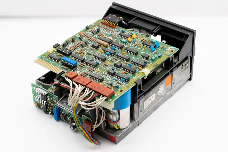
An electronic motor protection relay (EOR) hits ±1-5% trip-current accuracy and adds phase loss, phase imbalance, locked-rotor and stall detection that a bimetallic thermal overload relay (TOR) physically cannot provide, and the gap is widening as microprocessor-based models integrate Modbus and Ethernet diagnostics [S5][S2].
A bimetallic thermal overload relay remains the workhorse for small motors up to roughly 150A where cost dominates and load is predictable, while electronic units now cover 28-630A continuously and handle harsh ambient conditions without drift [S3]. For an overview of where these devices sit in the wider protection chain, see the motor protection relay reference.
Operating Principle: Heat-Bend Strip vs Current Transformer + Microprocessor
A bimetallic thermal overload relay passes motor current through a heater element wired in series with the motor, and the resulting heat bends a bimetal strip made of two dissimilar metals bonded together; once the bend exceeds the trip threshold, the mechanism opens the contactor coil circuit and stops the motor [S1][S4]. A "compensated" variant adds a second bimetal strip so both bend equally with ambient swings, preventing nuisance trips when the panel temperature is not the same as the motor's [S1].
An electronic overload relay replaces the mechanical trip path with current transformers or Hall-effect sensors feeding a microprocessor that models the motor's heating curve in firmware, executes the trip decision, and drives an output contactor [S2][S5]. This means the trip characteristic is a programmed i²t or vendor curve rather than a physical bending rate, and the same hardware can be re-rated for a different full-load-amp range by changing settings instead of swapping heater elements [S2][S3].
Accuracy, Repeatability and Ambient Sensitivity
Thermal overload relays carry roughly ±10-20% trip-current inaccuracy because the bimetal bend rate depends on the surrounding air temperature, on heater aging, and on the mounting orientation inside the cabinet [S5]. Non-ambient-compensated bimetallic units can nuisance-trip when the panel sits in direct sun or near a heat source, even though the motor itself is cool [S1].
Electronic overload relays hold ±1-5% trip-current inaccuracy and are not influenced by ambient temperature, because sensing is electronic rather than mechanical [S5][S3]. That same immunity is why electronic units are the default pick for outdoor pumping skids, rooftop HVAC starters, and tropical-plant MCC compartments where a TOR will chronically over- or under-protect [S3].
Functional Scope: Single-Function Overload vs Multi-Function Protection Relay
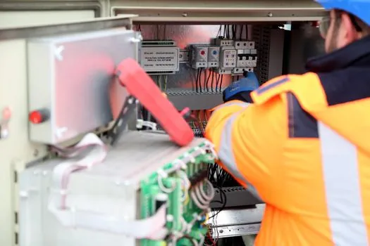
A bimetallic thermal overload relay is, in practice, a single-function device: it monitors current, integrates heat, and trips on sustained overload; it does not natively detect phase loss, phase imbalance, locked-rotor, stall, or ground fault [S5][S3]. Adding those protections requires separate protection relay devices upstream, which costs panel space and wiring.
An electronic overload relay bundles phase loss, phase imbalance, locked-rotor and stall detection into one device, and the higher-tier microprocessor models (for example Schneider TeSys T) add ground-fault detection, predictive maintenance logs, and communication over Modbus or Ethernet [S3]. For a deeper primer on how these multi-function devices compare to legacy thermal relay designs, the reference page lays out the functional split. Inside the iMCC line-up, an electronic unit can effectively replace a separate thermal relay plus a phase-monitoring relay, which simplifies the bill of materials [S3][S5].
Current Range, Reset Behaviour and Installation Footprint
Bimetallic thermal overload relays are commonly stocked from roughly 0.1A up to about 150A, and the trip current is set by swapping the heater element to match motor FLA, with manual or automatic reset selected by an H/A mode switch [S5][S3]. Once tripped, the bimetal must cool before reset, and repeated auto-reset cycles on a real fault will eventually damage the motor windings because the relay keeps re-energising into a hot motor [S1].
Electronic overload relays span a wider 28-630A range on a single frame, with the trip current set in firmware across the full range, no heater changes required, and reset behaviour configurable per application [S3]. The same hardware also reports last-trip data and running thermal capacity, which is what makes them a fit for unmanned or remote sites where a service call costs more than the relay itself [S2][S3].
Cost, Wiring Effort and Total Installed Price
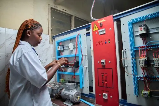
Thermal overload relays win on unit price and on simplicity: a bimetallic unit plus a matched contactor is the cheapest way to put a motor starter on the wall, and most electricians can wire, set, and troubleshoot it without specialist training [S3][S5]. For a 7-10A HVAC motor, a Schneider TeSys LRD14 is the typical low-cost pick in this class [S3].
Electronic overload relays carry a higher unit cost and need configuration through vendor software, which adds commissioning time and a dependency on the right handheld or PC tool [S5][S3]. That cost is recovered in plants where the relay replaces several discrete protection devices, where communication to the SCADA layer is required, or where downtime cost per hour outweighs the relay price [S2][S3]. When control cabinets run on tight scan budgets, see how an electronic overload relay fits into a wider scan and task architecture in this PLC scan time vs task cycle time reference.
Selection Criteria: When TOR Is the Right Pick, and When It Is Not
Use a bimetallic thermal overload relay when the motor is small (typically below 5-7 kW), the load profile is steady, ambient inside the panel is stable, and the goal is lowest installed cost with no communications requirement; standard pumps, fans, compressors, and conveyors are textbook fits [S2][S3][S4]. Avoid bimetallic units on critical-process motors, on motors with frequent starts, on high-ambient installations, and on any drive where phase loss or imbalance is a real risk, because the relay simply cannot detect those faults on its own [S5][S3].
Use an electronic overload relay when the motor is larger than roughly 5-7 kW, when ambient swings exceed what a compensated bimetal can handle, when the process is critical or the motor is in an inaccessible location, and when phase monitoring, ground fault, or SCADA communication is part of the spec [S3][S5]. For multi-motor intelligent MCCs where the relay also acts as an I/O node, the microcomputer protection page shows how these functions consolidate into a single intelligent device.
Limits, Failure Modes and What Each Relay Will Not Catch

A bimetallic thermal overload relay will not detect a single-phased supply on a three-phase motor quickly enough to prevent winding damage, because the bimetal still bends, just from a different heating distribution, and it cannot distinguish that case from a balanced overload [S1][S5]. It also drifts over time as the heater element ages and as the bimetal fatigues, so periodic trip-current verification is recommended on safety-critical applications.
Electronic overload relays shift the failure mode from mechanics to firmware and sensors: a failed current transformer, a corrupt parameter set, or a DC supply drop-out can disable the protection silently if there is no self-test routine [S3]. Vendor-specific firmware versions, communications card revisions, and compatibility with the contactor coil voltage should all be checked at the panel build stage, otherwise a perfectly specified relay can be a dead unit on first power-up [S3].
Comparison Matrix: TOR vs EOR Across Four Decision Criteria
On the four criteria that drive the buying decision, bimetallic thermal overload relays and electronic overload relays line up as follows: trip-current accuracy is ±10-20% for TOR versus ±1-5% for EOR [S5]; ambient-temperature immunity is partial (compensated units only) versus full [S1][S3]; current range tops out around 150A for TOR versus 630A for EOR [S3]; and functional scope is single-function overload for TOR versus overload plus phase loss, imbalance, locked-rotor, stall, ground fault, and optional Modbus/Ethernet for EOR [S5][S3]. Unit cost is lower for TOR, but total installed cost including the additional protection devices TOR cannot replace is often comparable on critical motors [S2][S3].
Verifiable Signals to Track Over the Next Quarter
Two signals are worth watching before specifying a fresh batch: first, whether electronic overload relay prices in the 28-150A range drop toward thermal-unit parity as more vendors push solid-state frames into the small-motor segment, since this would shift the cost crossover point for HVAC and light-industrial starters [S3]. Second, whether panel builders standardise on a single communication protocol (Modbus versus Ethernet/IP versus PROFINET) for the relay-to-controller link, because mixed fleets from different vendors remain a known integration pain point in brownfield MCCs [S3][S2].