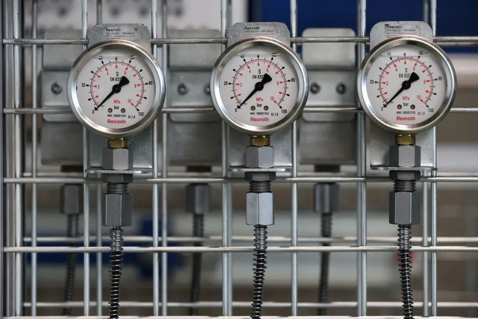
A construction-oriented electroslag pressure welding machine handles steel bar butt welds at 32 mm diameter and below, with the power supply specified at 380 V [S2].
Heavy electroslag welding can process pressure-vessel joints with thicknesses up to 120 mm, a limiting diameter of approximately 5,000 mm, and ingot weights up to 50 t [S1].
Two Diameter Classes Serve Different Jobs
Electroslag pressure welding capacity should be separated into construction rebar welding and heavy industrial or vessel welding. The two categories use related principles but have materially different machine scale, heat input, joint geometry, and acceptance requirements. [S3]
The Punair construction-machine specification identifies butt welding of steel bars at 32 mm diameter and below. Its power supply operates from a 380 V input, and the described system includes a flux box, upper and lower bar chucks, welding tongs, welding head, control box, and welding power supply [S2].
The 32 mm figure is a machine-level capacity, not a universal limit for electroslag welding as a process. A large electroslag welding installation for nuclear and non-nuclear pressure vessels handled wall thicknesses up to 120 mm, vessel diameters approaching 5,000 mm, and initial ingot weights limited to 50 t [S1].
How the Process Creates a Bar Butt Weld
The electroslag pressure welding process melts flux using the electric arc formed between the ends of the welded steel bars, producing high-temperature molten slag [S2].
For the construction process, the upper bar is released after the required melt condition is reached. Its downward movement displaces molten slag and liquid metal from the joint area, leaving a convex welded joint between the upper and lower bars [S2].
Published process temperatures require care because they describe different parts of the weld cycle. These figures should not be treated as a universal welding-heat-input setting or a permitted bar diameter.
For a technical comparison of the two scales, construction electroslag pressure welding is defined by a 32 mm bar limit and 380 V supply in the cited machine specification, whereas large vessel electroslag welding is associated with 120 mm thicknesses and an approximately 5,000 mm diameter limit [S1][S2].
Choosing Equipment Against the Required Diameter
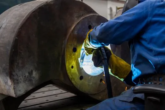
The controlling procurement value is the maximum bar diameter, but the bar diameter alone does not establish whether a machine will produce an acceptable joint. The machine must also grip the bar geometry, deliver the required current at the specified voltage, control the slag pool, and apply axial pressure at the correct stage of the cycle [S2].
Three decision criteria separate the main options. First, construction machines are specified around bars of 32 mm and below, with a lever-type single-column head or a screw-drive double-column head offered as alternative mechanical arrangements [S2]. Second, heavy vessel systems require capacity for much thicker sections, with a documented application extending to 120 mm plate thickness and approximately 5,000 mm vessel diameter [S1]. Third, acceptance evidence must match the product, because structural-bar performance data cannot establish the fatigue performance of a pressure-vessel weld.
A comparison of electroslag pressure welding with conventional fusion processes also depends on the required joint volume. Electroslag welding is presented as an automatic method for large longitudinal and circumferential welds in pressure vessels and chemical, refinery, and power equipment, where the purpose is to reduce production time while handling heavy sections [S1].
Capacity Does Not Remove Qualification Requirements
Electroslag welds require evaluation beyond visual confirmation of a completed joint. The heavy vessel process has technical requirements covering welding machines, auxiliary welding equipment, heat treatment, and defectoscopic nondestructive testing, as well as worker qualification [S1].
Mechanical performance also depends on joint geometry and preparation. The research program used electroslag welds made along the long dimension between steel plates measuring 2 ft 0 in by 1 1/4 in by 3 ft 6 in [S3].
Texas Highway Department Research Report 157-1F covered research performed from September 1970 through August 1971 and was prepared by the Center for Highway Research at the University of Texas at Austin with a report date of December 1972 [S3]. These results support the material pair and specimen conditions tested, not an unlimited approval for every steel grade, diameter, stress cycle, or service temperature.
Heavy Vessel Welding Changes the Scale
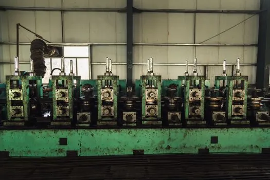
Large pressure-vessel fabrication shifts the engineering problem from joining construction reinforcement to producing thick, continuous vessel seams. The documented electroslag program addresses both longitudinal and circumferential joints, including the preparation of joints and the repair of defects [S1].
Its physical scale is explicit: weld thicknesses up to 120 mm, a maximum diameter of approximately 5,000 mm, and an ingot-weight limit of 50 t [S1]. The same technical review connects the process with reactor pressure vessels, chemical plant, refinery, and power-equipment fabrication [S1].
This scale makes the electroslag pressure welder selection problem a process-engineering decision rather than a catalogue lookup. For bars, verify the machine's stated diameter, bar length, electrode or contact arrangement, power supply, and control sequence. For pressure vessels, define plate thickness, joint orientation, welding position, heat-treatment route, nondestructive testing scope, and qualification requirements before accepting a supplier's capacity claim.
Limits, Failure Modes, and Traceable Capacity Claims
Three limits are visible in the technical record. Construction equipment in the cited specification stops at 32 mm bar diameter, heavy vessel electroslag welding reached 120 mm thickness and approximately 5,000 mm diameter, and the fatigue evidence applies specifically to A36 and A588 plate weldments tested at a 1 1/4 in thickness [S1][S2][S3].
The main failure concerns are incomplete penetration, inadequate fusion, slag inclusion, porosity, excess reinforcement, angular misalignment, and mechanical properties that do not match the base metal or service load. The cited process description explains why the slag pool and release sequence require control, but it does not establish defect-acceptance limits for a specific project [S2].
Any supplier claim should therefore be checked against the diameter being purchased, not against the largest vessel mentioned in historical literature. A 5,000 mm vessel-diameter capability does not establish a 5,000 mm rebar capacity, and a 32 mm bar machine does not establish suitability for a 120 mm pressure-vessel wall [S1][S2].
For procurement, the next traceable step is a written comparison of the required diameter and section thickness with the manufacturer's stated bar range, power supply, current or duty cycle, tooling geometry, weld-volume rate, consumables, and project-specific qualification evidence.