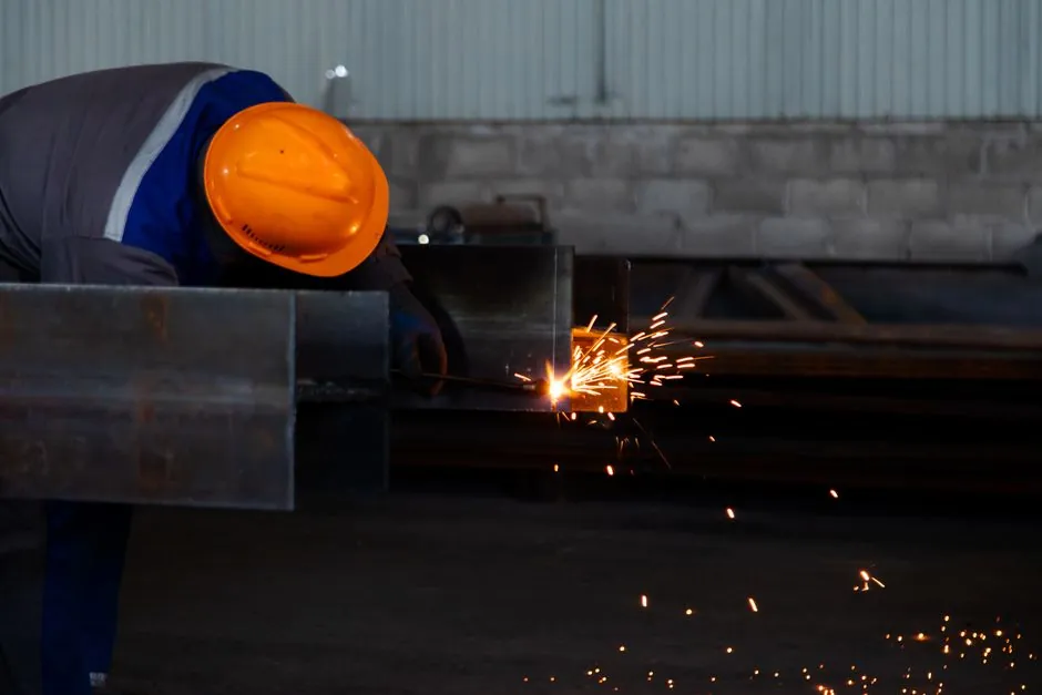
Reliable splicing requires more than crossing the machine’s minimum diameter: bar geometry, electrode and flux selection, heat control, end preparation, operator control, and inspection all affect the joint [S1][S3][S4].
What the 10–20 mm Range Means
A project still has to verify the welder’s bar capacity, acceptable material grades, power supply, and applicable welding procedure.
Rebar size must be specified as a nominal diameter and US designation together. The referenced splicing handbook lists #4 as 13 mm and #5 as 16 mm, demonstrating why metric and US bar designations should not be mixed without conversion [S1].
Compare Electroslag, Lap, and Mechanical Splices
Electroslag pressure welding offers a compact joint for vertical bars, whereas a lap splice transfers force through bond over a specified length and a mechanical splice transfers force through a proprietary connector [S4]. The three methods differ in field labor, congestion, and qualification demands.
Lap splices overlap two bars and may obstruct concrete placement, electroslag welding reduces the overlap but requires skilled labor, precision, and weld inspection, and mechanical splices add connector hardware while avoiding the molten joint process [S4].
Minimum Diameter Is Not a Complete Acceptance Test
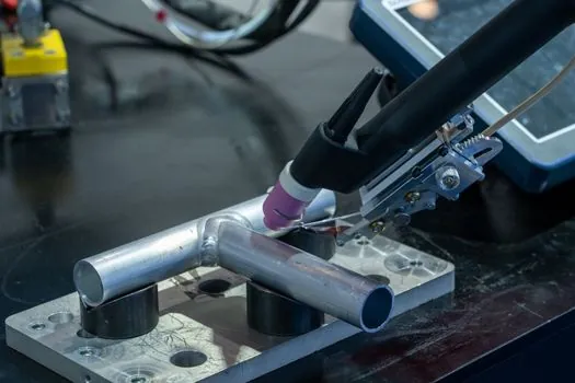
A minimum diameter does not establish reliable structural performance by itself. The 2022 large-bar study tested No. 14 and No. 18 bars, equivalent to 43 mm and 57 mm, under four-point bending, with concrete strengths of 34 and 69 MPa and target splice-failure stresses of 420–690 MPa [S2].
That research concerned lap splices rather than electroslag pressure welds, but it shows the scale of variables behind splice reliability. Eleven large-scale beams were tested, and transverse reinforcement was recommended throughout lap splices of 43 mm and 57 mm bars; even Ktr/db = 0.5 tended to reduce the observed size effect [S2].
For electroslag welding, the closer comparison is the electroslag process itself. A documented narrow-gap electroslag setup used 2.4 mm alloy-cored wire, while ESW-NG was described as approximately 19 mm gap, generally single-pass, vertical, and operating at a deposition rate of about 25 mm per minute [S3].
These figures show why diameter, electrode size, power, travel rate, slag depth, and joint fit are linked. Equipment selection should be checked against the detailed electroslag welder procedure, including automatic versus manual controls described in Automatic vs Manual Electroslag Pressure Welder Control.
Verify Bar Size, Steel Grade, and Procedure
Minimum and maximum diameters must be checked separately for the welder, its consumables, and the approved procedure. A machine may clamp a bar without producing an acceptable weld, particularly when electrode geometry or the available heat range does not match that diameter. [S2]
The project specification should therefore identify the exact bar grade and grade standard before the splice method is accepted.
The Dayton Superior handbook gives concrete size conversions for common bars, including #4 at 13 mm and #5 at 16 mm, but a table entry does not qualify a welding machine. Equipment documentation, a welding procedure specification, and applicable project acceptance criteria must all support the selected diameter [S1].
End condition also matters. Rebar ends should be prepared square enough to support uniform arc initiation and fusion, with misalignment, contamination, rust, scale, or surface damage removed where the procedure requires it.
Control the Weld Before Proving Bar Capacity
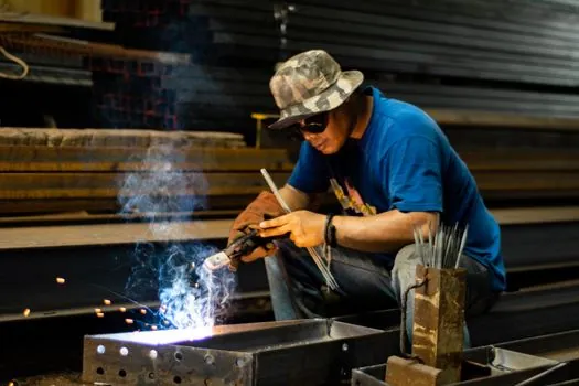
A narrow-gap electroslag weld requires a maintained molten slag layer of about 25 mm above the weld pool, together with a wire feeder, flux dispenser, cooling system, and suitable power supply [S3].
The process generates heat through electrical resistance in the slag. The documented electroslag description places the heated slag at approximately 1,930°C, while a sound ESW-NG joint was described as a vertical, generally single-pass deposit at about 25 mm per minute without preheat [S3].
Operational controls include keeping the consumable guide clear of the cavity walls, preventing a short circuit, maintaining a stable slag pool, and controlling heat extraction through suitable welding shoes or containment plates [S3]. Variability in these controls can produce lack of fusion, porosity, slag inclusion, or dimensional mismatch even when bar diameter is within the machine range.
Training and inspection close the remaining gap. Operators must be able to identify unstable arc conditions, incorrect flux addition, uneven wire feed, and shoe or end misalignment, while inspection personnel need a defined acceptance method for the completed splice [S3][S4].
Large-Bar Alternatives and Structural Limitations
For bars above 20 mm, electroslag pressure welding should not be accepted merely because the machine can physically handle the stock. The common application band cited for electroslag pressure welding stops at 20 mm, while lap-splice guidance is generally associated with bars under 25 mm and excludes Ø25 and Ø30 lap splices except in compression [S4].
Large-diameter reinforcement therefore needs an engineered route. The 2022 study examined 43 mm and 57 mm bars at concrete compressive strengths of 34 and 69 MPa, with target stresses of 420 and 690 MPa for 43 mm bars and 420 MPa for 57 mm bars [S2].
ACI 318-19 prohibits tension lap splices for bars larger than No. 11, or 36 mm, because of limited test data, while the study proposed bar-size factors of 1.15 for No. 11 and 1.25 for larger bars in development-length equations [S2]. It also recommended a minimum clear cover of one bar diameter for large-bar lap splices [S2].
These provisions concern lap splices, not electroslag pressure welds. Their value is as a warning: large-bar splice design can require direct testing, confinement, and project-specific engineering rather than extrapolation from a 10–20 mm field rule.
Standards, Qualification, and Acceptance
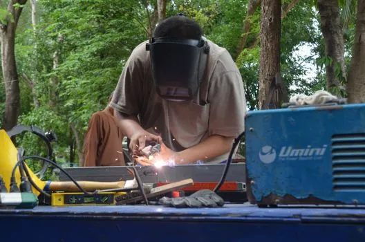
ESW-NG was accepted by AASHTO for common bridge steels and included in AWS D1.5:2010 with interim revisions, while AWS D1.8 addressed seismic structural welding through a separate inclusion effort [S3]. Project acceptance must use the code and edition adopted by the contract or authority having jurisdiction.
For reinforcing-bar electroslag work, the governing requirements can include the project welding procedure, material specifications, inspection plan, and the structural design criteria. The source material does not establish one universal minimum diameter, so 10–20 mm should not be presented as an unconditional code limit [S4].
The selection record should state the minimum and maximum nominal diameters, steel grade, electrode diameter and chemistry, usable joint geometry, available voltage and current range, slag capacity, cooling provisions, operator qualification, and inspection criteria. A 2.4 mm alloy-cored wire is documented for one electroslag setup, but it is not automatically the correct electrode for every bar within the 10–20 mm band [S3].
Track two signals before releasing production splices: successful qualification at the smallest specified bar size and the smallest specified steel grade, and repeatable completed-joint results at the largest specified diameter under field conditions. For procurement review, compare the electroslag pressure welder with the bar grades, positions, and production rate expected on site.