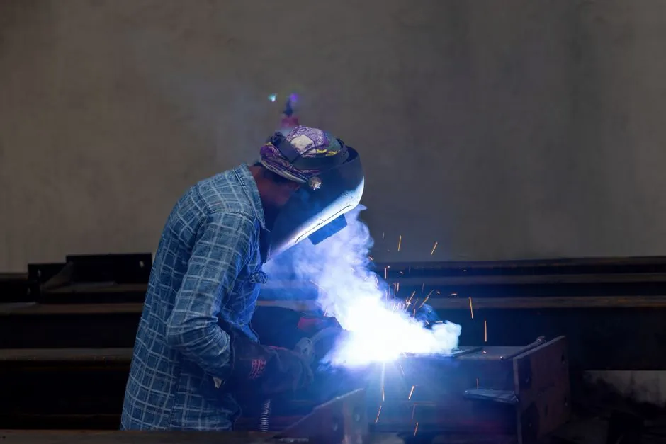
Electroslag pressure welding and mechanical coupling can both provide a direct steel-to-steel load path, but the comparison must be made on splice strength, ductility, slip, qualification, and installation control rather than nominal capacity alone.
This guide covers reinforcing-bar splices, with emphasis on large bars, congested reinforcement, seismic members, and fabrication environments. The governing project specification and local building code remain the final authority for any splice detail.
Define the splice systems and their load paths
Mechanical splicing joins two reinforcing bars end to end with a mechanical device, while a welded splice transfers load through a metallurgical joint between the bars. California Test 670 presents procedures for determining the mechanical properties of spliced reinforcing steel [S1].
Mechanical couplers join two reinforcement bars end to end and are used as an alternative to lap splices [S2]. A common threaded arrangement uses an annular sleeve around both bar ends; cold pressing can embed the deformations of the bar into the sleeve wall [S2]. Electroslag pressure welding is a fusion-welding process rather than a sleeve connection, so its acceptance depends on procedure qualification, weld quality, heat input, end preparation, and operator control.
The key distinction is that a mechanical coupler relies on sleeve geometry, bar surface engagement, thread or bolt mechanics, or a filling metal to transfer force. A welded splice relies on fusion and solidification of the steel. Neither should be selected by analogy with a lap splice, because a lap splice transfers force through bond in concrete while a direct splice transfers force through steel [S2][S5].
Compare strength, ductility, and slip
That figure is a code classification threshold, not proof that every coupon or every splice will achieve identical behavior.
These results are specific to the tested specimens, materials, loading, and geometry; they should not be generalized into a universal ranking without matching project conditions.
The comparison is therefore conditional. Mechanically coupled specimens showed less average ductility loss than GPW specimens in the cited experiment, but the study does not make electroslag pressure welding equivalent to GPW. Electroslag weld geometry, slag formation, fusion quality, and heat-affected properties must be evaluated on their own qualification and test data [S1][S4].
Select by field conditions and workforce capability
Mechanical couplers are the stronger option when bars cannot safely be welded, when reinforcement must join bars that cannot both rotate, or when a through-form or phased-pour connection requires a sleeve system. Position couplers address cases in which a cage bar must meet a bar already cast in place, while transition couplers accommodate a change in bar size [S5].
Electroslag pressure welding is better suited to weldable reinforcement, large bars, and production-controlled fabrication where end alignment, equipment capacity, slag control, and trained operators can be maintained. The equipment procedure must be matched to bar diameter and section; electroslag pressure welding settings by bar diameter is relevant when defining voltage, current, wire feed, and cycle parameters for a controlled production system.
A mechanical coupler is also a poor choice if the contractor cannot perform its required end preparation accurately or verify thread, swage, or bolt condition in the field. Threaded couplers require matching tapered or parallel threads, and thread design must account for the bar section removed by threading [S5]. Electroslag welding is a poor choice if bars are not weldable, surfaces cannot be prepared consistently, or the available apparatus cannot maintain the qualified process.
Apply test geometry and acceptance controls
California Test 670 specifies a tensile test machine able to apply a tensile force greater than the sample's ultimate tensile strength, with the machine required to be accurate and calibrated in accordance with ASTM A370 [S1]. California Test 670 references ASTM A370 and ASTM A706/A706M and specifies a slip-measuring device consisting of two calibrated dial indicators that measure displacement across the splice to the nearest 0.001 in. [S1].
These dimensions are test-method requirements, not construction layout dimensions. They matter because specimen geometry, grip distance, coupler length, and alignment can change the measured peak load, slip, and elongation at rupture [S1].
Understand installation risks and failure modes
The most obvious mechanical-coupler failure modes are pull-out, inadequate thread engagement, sleeve movement, bar misalignment, and damage from incorrect end preparation. The most obvious welded-splice failure modes are lack of fusion, excessive slag, undercut, overlap, insufficient fusion penetration, excessive heat input, and misalignment [S1]. Inspection procedures should identify which mechanism is being controlled rather than applying a generic pass or fail rule.
Field welding also introduces environmental controls, including surface condition, condensation or moisture, wind, temperature, and the ability to maintain a stable process. Those controls are not interchangeable with a sleeve installation check. In a cold or wet fabrication environment, a coupler may offer more repeatable site assembly, but only if the bars, threads, sleeve, and installation tool remain clean and undamaged [S2][S5].
For seismic design, ductility and cyclic performance are more important than a single static pull. Mechanical splices can preserve a load path without relying on concrete bond, which is valuable in plastic-hinge regions, but system approval and cyclic qualification remain necessary [S2][S3]. For welded reinforcement, the accepted weld procedure and splice detail determine whether the connection can support the intended deformation demand.
Base the decision on code, cost, and verification
CSA A23.3 permits mechanical and welded splices and requires a full mechanical splice to exceed the specified yield-strength demand for the applicable condition [S5]. CSA W186 covers welding of reinforcing steel, including the requirement for qualified procedures and welders [S5]. ACI 318-19 and the project specification govern in jurisdictions adopting ACI requirements [S2].
Mechanical coupling carries a product and installation cost, while electroslag pressure welding carries equipment, consumables, preparation, operator, and inspection costs. Bar diameter, splice quantity, labor rates, rejection risk, and the value of avoiding concrete congestion should be included in the comparison. For couplers, the relevant products and installation tools include rebar threading machines and rebar cutters, both of which can affect end-condition consistency.
Do not approve either method from a catalog strength alone. Require the exact bar grade and diameter, splice classification, test data, installation or welding procedure, inspection plan, and project-specific approval. Track pass rate, slip or elongation results, rejected welds or couplers, and correction time during initial production. These signals expose whether the selected process is functioning consistently before a larger placement phase creates a costly replacement problem.