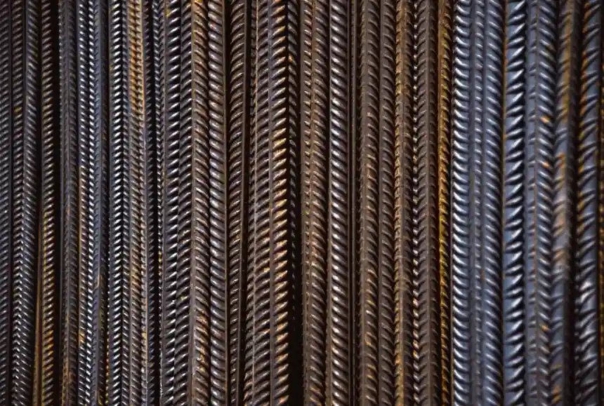
Fatigue-rated mechanical rebar couplers must demonstrate performance at 2 million load cycles, with assessment covering static strength, slip, S-N behavior and seismic low-cycle loading [S3].
EAD 160129-01-0301 applies to couplers used in mechanical splices of reinforcing steel bars, while nVent identifies bridges, railways, wind turbines and offshore platforms as structures exposed to dynamic forces.
What the 2 Million-Cycle Assessment Covers
The 2 million-cycle requirement is a defined fatigue assessment point, not a generic description of long service life. EAD 160129-01-0301 identifies fatigue strength at N = 2·10^6 load cycles as an essential characteristic and assessment item for couplers used in mechanical splices of reinforcing steel bars [S3].
The same assessment framework separates several performance checks: resistance to static or quasi-static loading, slip under static loading, slip after static loading, fatigue strength at 2 million cycles, S-N curve parameters under EN 1992-1-1, specified S-N parameters, and resistance to low-cycle loading associated with seismic actions [S3].
That separation matters. A connector can satisfy a static tensile requirement while still leaving questions about repeated-load degradation or displacement after initial loading. The European Assessment Document, dated May 2024, addresses these as distinct characteristics rather than treating strength as a single pass-or-fail result [S3].
Static and Cyclic Tests Build the Evidence
A fatigue qualification program should combine static tensile tests, cyclic tensile tests and low-cycle fatigue tests on reinforcement bars with and without couplers [S2]. Testing plain bar establishes the baseline behavior of the reinforcement system, while coupled specimens reveal whether connection geometry, thread form, friction or related details create a fatigue weak link.
This is consistent with the wider method: an S-N curve plots stress amplitude against cycles to failure, and its shape is used to identify fatigue limits and compare products rather than relying on a single load result [S4].
For welded joints in cold-twisted deformed bar, a 1991 study reported an estimated fatigue-limit range at 2 million cycles, expressed in ksi stress range, reinforcing the need to compare joints on a common stress-cycle basis [S1]. That historic dataset is useful context, but welded and mechanical connections must not be treated as interchangeable without product-specific evidence.
Threaded, Swaged and Welded Coupler Options
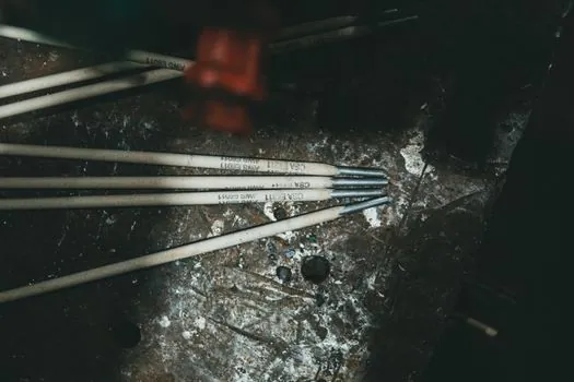
Threaded couplers are the most direct option for a 2 million-cycle specification when their submitted test data and product qualification support that duty. A search-result snippet describes ISO 15835 as the gold standard for high-cycle fatigue and states that couplers must withstand two million cycles of fatigue loading without failure. Threaded systems also fall within the mechanical-splice category addressed by EAD 160129-01-0301 [S3].
Swaged couplers provide a compression-based mechanical connection, but their fatigue position must be established from the relevant S-N curve rather than inferred from static strength. nVent LENTON's 2024 article states that its patented taper-threaded Ultimate coupler system offers superior fatigue results over similar solutions and performance above the Eurocode requirement.
Welded couplers are a separate connection class with their own fatigue-limit evidence. Research on welded joints in cold-twisted deformed bar produced estimated fatigue limits at 2 million cycles, but mechanical coupling performance cannot inherit those values unless the welded detail and material condition correspond to the tested assembly [S1].
For access to the terminology and mechanical details of the rebar coupler, use the comparison framework below:
Welded systems require evidence tied to the welded joint geometry and reinforcement condition [S1]. All three must also be checked for static resistance, slip and low-cycle loading under the applicable assessment framework [S3].
Where High-Cycle Fatigue Matters
Repeated loading is the defining condition in bridges, railways, wind turbines and offshore platforms, where dynamic forces act on structural components over long service periods [S4]. Couplers in these structures may sit in reinforcement cages, bridge decks, towers, foundations or other elements exposed to millions of load repetitions rather than a small number of large events.
The intended structure determines the severity of the cyclic spectrum. A single high-amplitude earthquake event is a low-cycle concern, while repeated traffic, wave, wind or machine-induced stress cycles are high-cycle concerns. The EOTA framework keeps these cases separate through distinct fatigue and seismic low-cycle assessment methods [S3].
Other materials can provide useful comparison points, although they are not direct substitutes for steel coupler qualification. A 2024 study found that ribbed GFRP reinforcement bars withstood 2 million fatigue cycles at a 40% stress ratio [S6]. That result concerns GFRP bars, not mechanical steel couplers, so it cannot validate a coupler's fatigue class.
Limits and Failure Risks in Coupler Selection
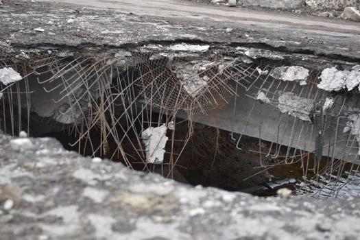
A coupler that meets 2 million cycles at one stress level is not automatically acceptable at every stress level. Fatigue capacity is represented by the relationship between stress amplitude and cycles to failure, so the qualification envelope must cover the load range expected in the structure [S4].
Slip is a separate failure concern from rupture. EAD 160129-01-0301 calls for slip under static or quasi-static loading and residual slip after that loading, as well as separate fatigue and seismic assessments [S3]. A specification that cites fatigue strength alone therefore leaves important connection-serviceability questions unresolved.
Test equivalence also requires care. The EOTA document permits fatigue evaluation through cycle testing and S-N parameter estimation, while ISO 15835 is presented as the high-cycle standard requiring 2 million cycles without failure [S3][S7]. The contract specification should identify the governing assessment document, bar diameter, grade, connection configuration and test regime rather than relying on the phrase fatigue rated.
One further distinction is material: GFRP bars, welded steel joints and mechanical steel couplers have different stiffness, damage mechanisms and qualification evidence. Their cycle counts may share the number 2 million without implying equal performance.
Procurement and Verification Requirements
Specify the cycle count, stress range or S-N basis, bar grade, diameter, coupler type and acceptance criterion in the purchase document. EAD 160129-01-0301 provides a detailed structure for assessment, covering static or quasi-static resistance, slip, fatigue at 2 million cycles, S-N parameters, low-cycle loading, reaction to fire and production-control responsibilities [S3].
For procurement based on the component's function, the rebar threading machine used to prepare the bar ends is part of the execution chain, but machine accuracy does not replace verification of the complete coupled assembly. Thread geometry, bar condition, engagement and installation all contribute to the tested system.
Requested submittals should identify the applicable standard or assessment document, laboratory evidence, tested configuration and any extrapolation beyond it. For mechanical alternatives, the comparison with electroslag pressure welding becomes relevant only when a project permits both connection methods and requires equivalent fatigue, static strength and installation criteria.
The direct comparison between mechanical and welded reinforcement systems is covered in Electroslag Welding vs Mechanical Couplers for Rebar Strength, including why connection choice cannot be reduced to tensile capacity alone.
The trackable verification signal is documentary: a supplier's 2 million-cycle claim becomes meaningful when tied to an S-N curve, the stress range tested, the reinforcement grade and diameter, the coupled detail, and applicable assessment provisions [S3][S7].