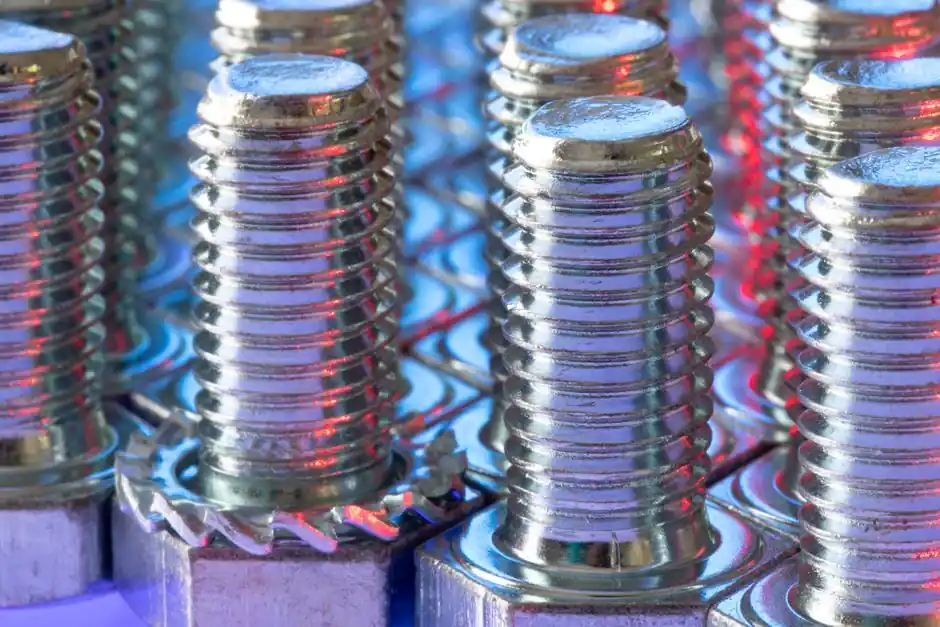
An extended-thread positional coupler uses one lengthened thread end and one standard thread end, connecting two reinforcing bars without relying on surrounding concrete for load transfer [S4].
The arrangement suits long, straight, large-diameter bars installed on site, where an ordinary coupler may leave insufficient engagement or inadequate handling clearance [S2][S4].
How a Positional Coupler Differs from a Standard Splice
A standard parallel-thread splice connects two conventional threaded ends through a female coupler, with both bars free to move and rotate before final tightening [S4].
A positional splice instead combines one standard thread end with one lengthened thread end [S4]. That asymmetry supports connection where the bar or cage cannot be freely rotated into a conventional coupler alignment [S4].
The rebar coupler therefore serves as a direct steel-to-steel load path instead of reproducing the force transfer of a lap splice through concrete bond [S1]. Positional couplers are identified as a distinct coupler class in the European Assessment Document covering mechanical splices of reinforcing steel from 8 mm to 50 mm [S6].
Selection Criteria for Longer Coupler Engagement
Bar diameter, thread form, coupler outside diameter, engagement length and tightening torque must be matched as one system rather than selected independently [S4].
Oriental Metals states that its mechanical rebars couplers and threads are used in reinforced concrete structures to replace normal rebar lap joints [S4].
A positional or extended version therefore requires a project-specific check of physical clearance, installation access and the approved coupler geometry.
The rebar threading machine used for production must form the matching male thread without reducing the required root section, while the coupler body must withstand the full design action rather than acting as a simple pipe sleeve [S1].
Parallel, Tapered and Extended Configurations Compared

Extended parallel-thread couplers are intended to create a full-strength mechanical joint for long, straight, large-diameter reinforcement installed on site [S2].
Parallel-thread couplers use matching male and female threads that are screwed together and tightened with a wrench [S4]. Tapered-thread couplers are available from 12 mm to 50 mm and are intended for rapid site installation, including work where long lap lengths would be difficult to accommodate [S7].
The main comparison is installation geometry, thread preparation and adjustment range. A parallel system offers straightforward male-to-female engagement; a tapered system supports rapid assembly; an extended positional system adds longitudinal reach or engagement to solve a specific cage-connection problem [S2][S4][S7].
Thread preparation also differs operationally. A parallel-thread coupler can use rolled or upset-forged bar ends, while tapered-thread systems require bar-end preparation matched to the taper geometry [S1][S3]. Neither configuration removes the need to comply with the manufacturer’s approved installation instructions and project specification.
Field Applications and Installation Sequence
Positional couplers are used to join two bars [S6].
This makes positional geometry useful for prefabricated cages, bridge reinforcement and other assemblies where bar ends cannot be freely brought into line.
Quality Control and Failure Prevention

After tightening, exposed thread should not exceed half the coupler length plus 2 to 4 mm, with the allowance depending on bar diameter [S8]. This check limits incomplete engagement, while excessive exposed thread can indicate that the bars have not advanced far enough into the coupler.
Couplers for mechanical splices of reinforcing steel bars cover sizes ranging from 8 to 50 mm [S6].
Threaded couplers for Grade 60 rebar are described as exceeding 125% of the specified yield strength, with connection behavior intended to achieve full bar-break performance [S1]. Applicable project frameworks include ACI 318, ISO 15835 and Eurocode 2, but approval must be tied to the exact coupler system and governing project jurisdiction [S1].
For further selection context, the comparison of electroslag welding versus mechanical couplers evaluates another route to a continuous reinforcement load path and helps define when a positional threaded system is the appropriate mechanical-splice solution.
Standards, Testing and Procurement Requirements
The European Assessment Document for couplers covers mechanical splices of reinforcing bars with diameters from 8 mm to 50 mm and includes positional couplers as a defined type [S6].
For structural verification, threaded mechanical splices are associated with ACI 318, ISO 15835 and Eurocode 2 [S1]. The cited Grade 60 performance exceeds 125% of specified yield strength, while connection qualification is based on full bar-break performance rather than coupler failure [S1].
Procurement records should state bar diameter, grade, thread type, pitch, lengthened-end arrangement, coupler outside diameter, minimum engagement, installation tool and required torque [S4][S5]. A generic “extended coupler” description is not sufficient because dimensions and thread forms vary across systems, and the available catalog range spans 13 mm to 50 mm [S4].
Installation records should document the inspected thread and coupler condition, achieved engagement, exposed-thread limit and tightening procedure. Those five checks close the gap between a catalog dimension and an installed structural connection [S4][S8].
The next procurement decision is measurable: match the project’s bar diameter and grade to an approved extended positional coupler, verify the specified engagement against the physical cage geometry, and require the supplier to confirm the applicable standard and test performance before fabrication.