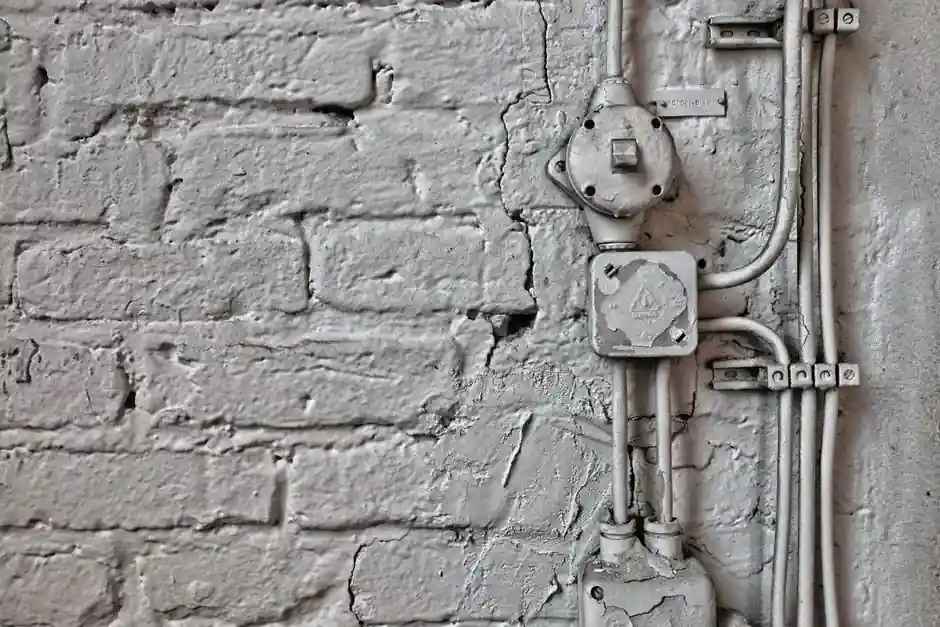
Explosion-proof cable glands maintain the flameproof integrity of Ex d enclosures by sealing the cable entry, clamping the armor, and providing a controlled flame path that cools escaping hot gases below the auto-ignition temperature of the surrounding atmosphere, per IEC 60079-1 [S2].
Selection is driven by cable type (armored vs non-armored), area classification (ATEX Zone 1/2/21/22 or NEC Class I/II Division 1/2), ingress protection target (typically IP66/IP68), and body material, with brass, stainless steel 316L, and aluminum as the three standard options across oil and gas, chemical, marine, and grain-handling sites [S1][S4][S6].
How the Flame Path and Dual Seals Work
The gland's safety function is containment, not prevention: it must survive an internal deflagration and stop the flame front from reaching the external atmosphere, as defined by IEC 60079-1 for 'd' (flameproof) enclosures [S2]. The engineered flame path is a precisely toleranced gap, typically machined to within 0.1-0.2 mm width over a defined length, that quenches the burning gas by allowing heat to transfer to the metal walls before the gas exits [S2].
A modern Ex d cable gland carries two independent seals: an outer elastomeric sealing ring (neoprene or silicone) compressed onto the cable outer sheath for IP66/IP67 environmental protection, and an inner sealing sleeve around the cable bedding or inner jacket that maintains the flameproof barrier even if the outer seal is compromised [S2][S7]. For armored cables such as SWA (Steel Wire Armored) or MC-HL, a cone-and-ring armor clamp grips the metal braid and provides the equipotential bonding path required for grounding continuity [S2].
Armored vs Non-Armored vs Barrier: Picking the Right Type
Three construction types dominate the market, each mapped to a different cable and zone profile. Compression glands suit non-armored cables in Zone 2 / Class I Division 2 where the enclosure itself is not flameproof. Armored (compression-with-claw) glands add a metal armor termination for SWA, STA, or MC-HL cable and are the workhorse for onshore oil and gas and mining. Barrier (compound-filled) glands use a two-part epoxy or resin fill around the cable cores to seal the entry against gas migration along the cable cores, and are mandatory in IEC 60079-1 for most Ex d installations and in many Ex e (increased safety) panels where the cable is run through Zone 1 [S5][S6].
Specification must match the cable OD range to the gland's sealing range (often a 2-3 mm window per gland size), with metric thread forms M20, M25, M32, M40, M50, M63, and M75 covering most enclosures; NPT 1/2" through 3" equivalents are stocked for NEC-spec projects [S1][S3]. Mis-matched OD is the single most common field failure mode, with undersized cables bypassing the seal and oversized cables preventing the compression ring from reaching its design compression set [S2][S4].
Material Selection: Brass, 316L Stainless, Aluminum
Body material is selected by corrosion environment, weight limit, and cost. Brass (CW614N / CW617N, often nickel-plated) is the default indoor and light-outdoor choice, offering good conductivity for the grounding path and low cost. Stainless steel 316L is specified for offshore, chemical, and washdown-down food-grade lines where chloride pitting and galvanic attack of brass are unacceptable [S4][S6]. Aluminum (marine-grade) variants are common in lighting fixtures and on offshore modules where weight is critical, but require careful isolation against dissimilar-metal contact with stainless enclosures.
Elastomer choice is equally critical: silicone seals run from approximately -60 °C to +180 °C and are required for cold-climate LNG and arctic projects, whereas standard neoprene is rated roughly -30 °C to +90 °C and is the default for temperate-zone installs [S2][S5]. Specifiers should always cross-check the elastomer compatibility with the cable jacket material (PVC, PE, XLPE, EPR) to prevent long-term chemical attack that would degrade the IP rating over years of service.
Certifications, Standards, and Area Classification
A gland that enters an Ex d enclosure must carry the same protection level as the enclosure, since it is part of the flameproof barrier. The three governing certification systems are ATEX 2014/34/EU (EU), IECEx (global), and the NEC 500 / CEC system (North America), with each gland marked for its gas group (IIA, IIB, IIC) and dust group (IIIA, IIIB, IIIC) [S1][S2][S3]. For Group IIC hydrogen and acetylene atmospheres, the flame path gap tolerance tightens to the most restrictive level, and not every brass gland is certified to IIC; the certificate must be checked for the exact gas group and ambient range.
For the US market, NEC 500 requires that cables entering an explosion-proof enclosure in Class I Division 1 be sealed at the point of entry, with a sealing fitting (often a barrier gland) within 18 inches of the enclosure, per the Eaton hazardous-location white paper [S3]. In Class I Division 2, a standard industrial cable gland meeting the enclosure's listed ingress rating is generally acceptable since the enclosure itself is not flameproof. Independent third-party markings from UL, CSA, BASEEFA, or PTB should be visible on the body, and the certificate number should be traceable to the manufacturer's datasheet.
Installation Pitfalls and Inspection Cadence
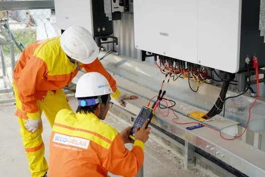
Most premature gland failures are installation errors, not manufacturing defects. The four highest-frequency problems observed in field audits are: incorrect torque on the back nut (under-torque leaves the seal uncompressed, over-torque splits elastomers or strips threads); use of PTFE tape on the entry thread (Teflon fragments can prevent the metal-to-metal flame-path contact required by IEC 60079-1); pairing a metric-thread gland with an NPT enclosure (or vice versa) without a certified thread adapter; and re-using a compression-type gland after cable replacement without renewing the sealing ring [S2][S4].
A defensible inspection cadence is annual visual inspection for cracked seals and corrosion, with a torque verification on the back nut, plus a 3-year thermographic survey on energized enclosures to spot hot joints before they become ignition sources. For barrier glands, the compound fill cannot be re-entered without cutting out the old pour and re-terminating, so barrier glands are typically specified only on cables that are not expected to be changed during the plant's service life, with compression glands used on the removable-cable side of equipment [S3][S5].
Sourcing, Lead Time, and Cost Signals
Stock ATEX/IECEx double-sealed cable glands in M20-M40 brass with neoprene seals are the easiest items to source, with multiple Chinese and European manufacturers (including SUREALL, CMP, Hawke, and Ex Industries) holding standard SKUs at lead times of 2-6 weeks for small lots [S1][S6]. Non-standard combinations - 316L body with silicone seals in IIC certification, NPT threads, or barrier (compound) variants - extend lead time to 8-12 weeks and are typically built to order. For a related decision on the Ex d side, see this comparison of barrier vs compression glands for Ex d enclosures.
Buyers should validate three things before issuing a PO: the certificate scope (group, ambient, IP), the cable OD range stamped on the gland body or datasheet, and the entry thread form. Skipping any of these is the documented root cause of most field non-conformities raised under IEC 60079-14 inspection regimes. The next signal worth tracking is the rollout of unified IECEx Ex e / Ex tb certified hybrid glands that accept both armored and non-armored cable in a single body, which would simplify spares stocking for EPC contractors operating in mixed-classification sites.