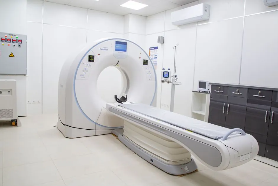
Line-detector fan beam CT (FBCT) and flat-panel cone beam CT (CBCT) diverge most sharply when the workpiece is dense: high-attenuation materials such as steel, Inconel, and titanium drive scatter fractions that overwhelm CBCT flat-panel reconstructions, while FBCT's collimated line geometry suppresses that scatter and preserves dimensional accuracy [S5].
For industrial NDT buyers, the decision is geometry, detector, scatter behavior, and total scan time, not raw resolution on paper: cone beam CT can match or exceed FBCT spatial resolution on low-density samples, but on dense parts the scatter ratio inverts the trade and pushes buyers back to line-detector systems [S1][S5].
Beam Geometry and Detector Architecture
Fan beam CT collimates the X-ray output into a thin fan that strikes a curved or linear detector array, typically 16 to 320 rows and roughly 1,200 sensors per row, then completes a full 360° rotation around the part [S4]. The narrow, in-plane fan shape means most scattered photons exit the detector plane and are rejected by the collimation, which is the underlying reason scatter contamination stays low even on thick steel sections.
Cone beam CT diverges a cone-shaped beam onto a single flat-panel detector, so the same projection captures the full volume in one rotation, often limited to an arc under 240° rather than a full 360° sweep [S4][S5]. That single-shot geometry is the source of both CBCT's speed advantage and its scatter vulnerability: every voxel along the cone path contributes scatter to every detector pixel. For dense parts, this geometry inflates scatter-to-primary ratios well above what collimated line geometry produces [S7].
Scatter Behaviour and Image Quality on Dense Workpieces
Scatter is the dominant failure mode in CT of dense industrial parts, and Quality Mag's 2021 NDT feature explicitly states that cone beam radiography is much faster than fan beam CT but less precise due to scatter radiation artifacts [S7]. Quality Digest's metrology comparison is more categorical: flat-panel detector CBCT is the best choice for low-density samples that do not generate significant scatter radiation, which by direct inversion means FBCT is the better choice when scatter is significant, exactly the dense-part regime [S5].
The peer-reviewed comparison by Lechuga et al. confirms the clinical analogue: under standardised protocols, FBCT produced superior images in clarity, uniformity, anatomical accuracy, and low-contrast resolution while delivering lower patient dose than on-board CBCT systems [S1]. The same physics that degrades CBCT contrast on dense anatomy, primarily elevated scatter and reduced low-contrast detectability, translates directly to the metrology case on high-attenuation castings and forgings.
Throughput, Cost, and System Footprint
Cone beam CT scans a full volume in a single partial rotation on a flat-panel detector, which cuts acquisition time and lets CBCT ride on a smaller, cheaper gantry than a 320-row line-detector system [S5][S4]. The AO Foundation's clinical comparison lists lower radiation dose, lower cost, fewer metallic-artifact issues, mobile 3D C-arm portability, and operation by non-radiologists as CBCT's structural advantages [S2].
Fan beam CT systems carry the higher capital cost and longer scan time, but they buy back that cost on dense parts: line collimation, anti-scatter hardware, and full 360° sampling are what keep HU values stable and voxel noise low on steel, copper-alloy, and nickel-superalloy workpieces [S4][S5]. For foundries and aerospace parts shops, that stability is what allows a measurement to be traced, not just visualised.
Selection Criteria: When to Choose Which
The first decision criterion is the part's effective attenuation: low-density work (plastics, aluminium, magnesium, honeycomb composites, additively manufactured polymer parts) routes to flat-panel CBCT for speed and cost; high-density work (steel castings, Inconel AM, tungsten carbide, copper-alloy valves) routes to line-detector FBCT for clean reconstructions [S5]. For a plant using line-scan camera based optical inspection upstream, pairing with FBCT downstream keeps the metrology chain on a consistent scatter-controlled architecture.
The second criterion is dimensional tolerance and metrology traceability. If the buyer needs voxel-level dimensional metrology on dense parts, the 360° sampling of a curved or linear detector array preserves the reconstruction assumptions that flat-panel partial-arc CBCT violates; the trade is scan time per part, which is the third criterion [S4][S5]. The fourth is footprint: a line-detector FBCT system typically demands a larger shielded cell and heavier gantry than a CBCT benchtop, which matters when the inspection cell is colocated with a conveyor sorting line or an automatic molding line output buffer.
Decision Matrix: Fan Beam CT vs Cone Beam CT for Dense Parts

Crowding the four decision criteria into a side-by-side read: on dense-part image quality, FBCT wins (line collimation and 360° sampling suppress scatter; CBCT degrades through cupping and streaking) [S5][S7]. On dimensional metrology traceability, FBCT wins (stable HU, full angular sampling, well-behaved reconstruction assumptions) [S1][S4]. On scan time per part, CBCT wins (single partial rotation versus multi-rotation line-detector acquisition) [S2][S4]. On system cost, footprint, and portability, CBCT wins (lower capital cost, smaller gantry, mobile C-arm form factor available) [S2].
For buyers sourcing resin sand line castings into aerospace or for buyers integrating inspection into a molding line end-of-line check, the default for dense workpieces is line-detector FBCT; CBCT earns its place only when the part is small, low-density, or when first-article visualisation is the deliverable rather than metrology. The Quality Digest piece draws the line directly: pick CBCT for low-density samples without significant scatter, pick FBCT for everything that generates significant scatter [S5].
Standards, Calibration, and Sourcing
All industrial CT data referenced here ships in DICOM format, the same Digital Imaging and Communications in Medicine standard used in medical imaging, which is why medical-grade metrology and clinical scanners share reconstruction pipelines and why buyers can move trained staff between modalities [S2]. Calibration phantoms, HU stability checks, and geometric accuracy tests remain the same regardless of beam geometry, but acceptance criteria on dense reference artefacts will separate FBCT from CBCT faster than any spec sheet [S4].
For buyers comparing HSLA vs Q&T alloy plate work flows, the same logic applies: tighter material spec drives tighter inspection spec, which drives the buyer from CBCT to FBCT. Equipment lifecycle coverage of dense-part inspection is detailed in our walkthrough of component-size 3D scanner FOV for small-part metrology, where line-detector systems remain the baseline reference.