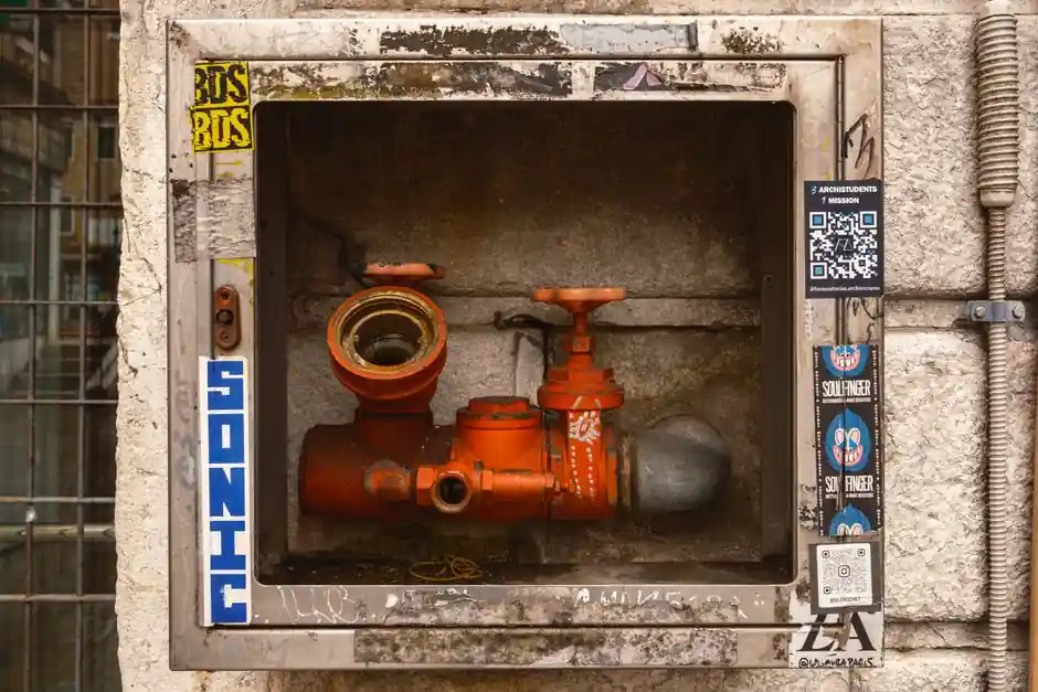
AWWA C502 dry-barrel hydrants use a compression main valve opening against flow and closing with flow, with an internal valve diameter of 5-1/4 in minimum and a 250 psi working pressure rating, per spec SEC02645 [S4]. The main valve assembly is the buried compression element that starts and stops flow, while the drain valve assembly automatically empties the barrel when the hydrant is shut, leaving the upper barrel dry and frost-free [S6].
Two (2) internal and two (2) external bronze-lined drain ports are required in the main valve assembly to drain the hydrant barrel, and the drain mechanism shall be designed to operate automatically with the main valve and allow a momentary flushing of the drain ports, per municipal spec language built on AWWA C502 [S4]. This is the fire hydrant cross-section that every specifier, water utility engineer, and fire-protection designer should be able to sketch blind.
Main valve and seat-ring geometry
The main valve seat shall be of bronze and the assembly into the hydrant shall involve bronze-to-bronze thread engagement, with two (2) O-ring seals as a positive pressure seal between the bronze seat ring and the shoe, and valve assembly pressure seals obtained without torque-compressed gaskets [S2][S4]. The seat ring sits in the shoe (also called the base or foot piece) and forms the lower pressure boundary of the barrel. The M&H 129 parts list puts this stack at items 35-44: upper valve plate (aluminum bronze), seat ring (aluminum bronze), seat-ring upper and lower O-rings (Buna-N #261, #255), main valve seat (Buna-N), and bottom plate retained with stainless lock washer and eight shoe hex bolts [S2].
Main valve removal is a one-tool, no-excavation job: hydrants shall be designed to allow removal of all operating parts through the hydrant barrel by means of a single, lightweight disassembly wrench without excavation [S4]. This requirement drives the upper-stem / lower-rod split and the frangible safety coupling just below the bonnet, which Kennedy Valve's US10612218B2 patent illustrates with a stem 106 running as a shaft between the main valve 102 and the upper stem assembly 101 [S1]. Main valve shall be made of synthetic rubber and formed to fit the valve seat accurately, not metal-to-metal [S4].
Drain valve assembly: how the barrel stays dry
When the hydrant is in the closed position the main valve lowers to block water passage and re-opens drain holes at the bottom of the hydrant, allowing residual barrel water to fall back into the shoe and out through the drain ports into the surrounding dry soil [S5]. The drain valve facing on the M&H 129 is EPDM (item 37) riveted to the upper valve plate with eight stainless rivets (item 36), and two bronze drain-hole bushings (item 48) line the ports in the shoe/retainer ring sub-assembly [S2]. The compression movement of the main valve is what uncovers and covers these ports, so there is no separate solenoid, cam, or secondary actuator: the same action that stops flow opens the drain.
Corrective action for a hydrant that fails to drain or that holds water in the barrel is to remove the main valve assembly and replace the drain valve facings; the typical cause is a damaged top O-ring on the seat ring, fixable by disassembly, cleaning, and lubrication per the Mueller reference manual [S3]. If a drain valve facing loses its EPDM resilience, the barrel can stay charged, freeze, and split the standpipe, which is why AWWA C502 hydrants are designed so the drain is mechanically linked to the main valve stroke rather than relying on a manual bleed.
Stem, safety coupling, and bonnet stack
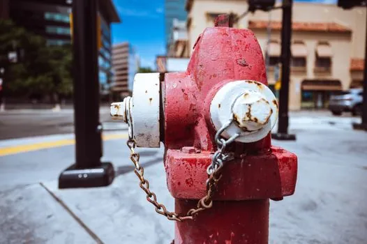
The operating stem is split into an upper rod (steel C1117 HFS with brass stem sleeve) and a lower rod (steel C1117 HF5) joined through a cast iron break coupling (item 28) held by two retaining clips and two clevis pins (items 26-27), and this break coupling is the sacrificial element that shears cleanly below the top of the barrel on vehicle impact [S2]. Above the break coupling sits the dry-top bonnet stack: hold-down nut (brass C87850), hold-down nut O-ring #331 (EPDM), operating nut (brass C87850), acetal thrust washer, six zinc-plated bonnet hex bolts and nuts, and a cast iron bonnet sealed with three bonnet/nozzle/standpipe O-rings #370 (Buna-N) [S2].
US10612218B2 (granted 2020-04-07, priority 2018-08-21, assigned to Kennedy Valve) protects a specific upper-stem nut and thread geometry intended to keep the operating stem sealed against moisture and grit ingress, which is the practical reliability problem the dry-top bonnet is built to solve [S1]. The dry top is specified to have a moisture-proof lubrication chamber providing automatic lubrication of threads and bearing surfaces each time the hydrant is operated, with a top O-ring as a dirt/moisture barrier and a lower O-ring as the pressure seal [S4]. The pentagon operating nut is 1-1/2 in point-to-flat, National Standard, opening counter-clockwise [S4].
Outlets, branch, and material selection
A traditional dry-barrel hydrant has two 2-1/2 in (65 mm) hose nozzles and one 4-1/2 in (115 mm) pumper nozzle; in some jurisdictions, notably downtown St. Louis, hydrants carry only a single pumper outlet [S5]. The branch pipe from the city main should be a minimum 6 in to limit pressure loss and permit greater flow capacity; older 4 in branches are a known flow bottleneck [S5]. The shoe uses a 6 in mechanical joint inlet connection to the supply main, and thrust blocking is required under any hydrant or valve where the stem joins the main to prevent movement from water flow forces, per FM Approval Standard DS 3-10 (2025-04) [S8].
Material choices in the M&H 129 stack illustrate the design pattern: ductile iron for the standpipe and shoe/retainer ring sub-assembly, cast iron for the bonnet, weather cap, hose caps, pumper cap, and safety flanges, brass C87850 for all wetted trim (operating nut, hold-down nut, hose/pumper nozzles), aluminum bronze for the upper valve plate and seat ring, Buna-N for the pressure O-rings, EPDM for the drain valve facing and the hold-down nut O-ring, and stainless steel for the small fasteners and rivets [S2]. Two of the three bonnet/nozzle/standpipe O-rings are exposed to pumped water on every operation, which is why EPDM molecular structure and crosslinking mechanism choices directly drive drain-valve facing life in field service.
Specification compliance and certification
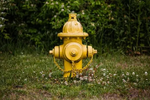
Dry-barrel hydrants under AWWA C502 are required to be tested at 250 psi working pressure and carry third-party listings; the M&H 129 is AWWA C502 compliant, NSF 61/372 certified, UL listed, FM approved, and carries a 10-year limited warranty on materials and workmanship [S2]. Color-coding per NFPA 291 classifies hydrants by available flow: Light Blue / Class AA for 1,500 gpm and above, Green / Class A up to 1,500 gpm, Orange / Class B up to 1,000 gpm, and Red / Class C for less than 500 gpm (NFPA 291-2019 5.2.1.2) [S5]. Municipal specs typically name four approved models: Mueller Super Centurion 250, M&H Style 129, U.S. Pipe M-94-250 psi, or American Flow Control B84-250 psi [S4].
Spec language to copy directly into a project spec: hydrants shall be three-way, post type, dry top traffic model with compression main valve opening against and closing in the direction of normal water flow; internal main valve diameter shall be minimum 5-1/4 in; main valve shall be made of synthetic rubber and formed to fit the valve seat accurately; main valve seat shall be of bronze and the assembly into the hydrant shall involve bronze-to-bronze thread engagement; minimum of two internal and two external bronze-lined drain ports shall be required in the main valve assembly to drain the hydrant barrel; drain mechanism shall be designed to operate automatically with the operation of the main valve and shall allow a momentary flushing of drain ports [S4].
Failure modes, troubleshooting, and field signals
Three field failure modes dominate dry-barrel hydrants: (1) the upper-stem O-rings (#218 Buna-N) wear and the lubrication reservoir leaks, allowing water into the bonnet; (2) the drain valve facing loses elasticity and the barrel does not fully drain, leading to freeze damage in cold climates; (3) the frangible break coupling shears on impact, which is by design and is what limits damage to the upper barrel in a vehicle strike [S2][S3][S5]. Mueller's troubleshooting guide flags a damaged top O-ring on the seat ring as the cause of drain-related failures and prescribes removal of the main valve assembly and replacement of drain valve facings [S3].
Two trackable signals for hydrant specification health: (1) verify that the drain ports actually flow when the main valve is cycled closed, by listening for the tell-tale whoosh as the barrel empties, and (2) check that the operating nut turns freely through a full revolution without binding, which confirms the dry-top O-rings and thrust washer are still sealing. A hydrant that does not drain, or that seeps from the bonnet, should be taken out of service until the main valve assembly is pulled and the drain facings and seat-ring O-rings are replaced [S3][S4].
Detailed specification references: locking assembly, and steel section.