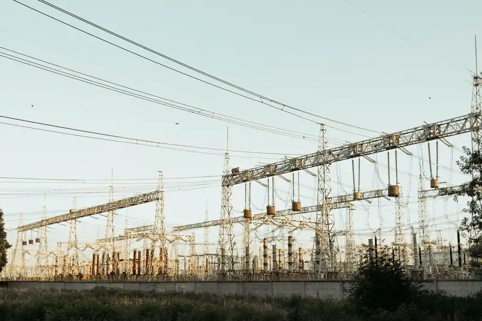
Fixed infrared (IR) non-contact sensors and contact wireless sensors target different failure signatures inside medium- and low-voltage switchgear, and selecting the wrong one typically means either a standoff safety risk or a blind spot in the thermal trend [S1][S5].
Both technologies compete for the same budget line, but their operating envelopes diverge: fixed IR reads from a distance with no galvanic path into the cubicle, while contact wireless sensors mount directly on the busbar, lug, or cable termination and stream temperature over RF. Picking between them is a function of how many points you need, whether line-of-sight is achievable, and whether the application demands a trend or a single spot reading [S2][S6].
Operating Principle and Sensing Mechanism
Non-contact IR sensors convert emitted thermal radiation from a target surface into a temperature reading using a thermopile or pyroelectric detector, with no physical contact between sensor and conductor; accuracy on typical fixed-mount industrial units is stated in the ±2% of reading or ±2°C class, with a 240 ms response time on compact OEM models [S2][S7].
Contact wireless sensors in switchgear are almost always surface-mounted thermistor or RTD elements bonded to the conductor; they require good thermal coupling to the bolted joint or termination they are intended to monitor, and they transmit temperature data via 433 MHz, 868 MHz, 915 MHz, or 2.4 GHz ISM-band radios to a gateway, with passive (battery-free, SAW or inductively-coupled) variants eliminating the battery replacement cycle entirely [S3][S8].
Where Each Technology Fits the Cabinet
Fixed IR non-contact sensors are the right match when a few known hot joints must be monitored from outside an energized, closed panel: a breaker stabs lug, a specific cable termination, or a single bolted busbar joint, with the sensor aimed once and read continuously over 4-20 mA or thermocouple output to a PLC, BAS, or IoT gateway [S2].
Contact wireless sensors are the right match when you need to monitor many bolted joints across a lineup, MCC, or substation, especially inside compartments a fixed camera cannot see line-of-sight, and the points are accessible for direct surface mounting; passive (battery-free) wireless units install in under 20 minutes per point and stream continuous data 24/7 [S2][S8].
Selection Criteria: Standoff, Point Count, Output

Selection comes down to four engineering numbers: standoff distance, points to monitor, output interface, and enclosure rating; a typical fixed-mount industrial IR sensor covers -20°C to 500°C with a 4-20 mA loop-powered output and an IP65 stainless body, while a contact wireless sensor covers -40°C to +125°C joint temperature with an RF link to a gateway, and typical mounting is adhesive, epoxy, or magnetic [S2][S5].
For MV switchgear specifically, the published guidance from June 2026 is explicit: IR non-contact sensors are suitable for periodic inspection walks only, and accuracy degrades with distance and viewing angle, and blocked line-of-sight, which is why continuous thermal monitoring of bolted joints is done with contact wireless rather than fixed IR [S6].
Comparison: Fixed IR vs Contact Wireless on 4 Criteria
On standoff safety, fixed IR wins because the sensor body never touches an energized conductor, while contact wireless requires a planned-outage surface mount on the joint it is reading; on point count, contact wireless scales to dozens of joints per gateway, while fixed IR cameras or point sensors are cost-effective only for a few known hotspots [S2][S5].
On trend visibility, contact wireless delivers 24/7 continuous data versus annual thermography for IR-only programs, and the trend is what catches a loosening bolt before it cooks; on accuracy, contact wireless bonded directly to the busbar typically reads within ±1°C to ±2°C of the true joint temperature, while fixed IR accuracy depends on emissivity setting, target distance, and a clean optical path, and a fixed camera can lose the joint if the field of view shifts or the cabinet door is closed [S2][S5][S6].
Limitations, Failure Modes, and EMI Behavior
Fixed IR fails when the optical path is blocked (dust on the lens, closed cabinet door, obstructed line-of-sight) or when target emissivity is mis-set; high-voltage switchgear in metal-clad panels frequently denies the camera a clean view of the bolted joint, which is why fixed IR is often paired with periodic handheld thermography rather than relied on as the sole continuous monitor [S5][S6].
Contact wireless sensors in switchgear face a documented EMI challenge: high electromagnetic interference in switchgear can disrupt wireless signal transmission, especially for passive wireless systems, leading to data loss or inaccuracies, and surface-mounted sensors may suffer from poor thermal contact with high-voltage components, causing delayed or distorted readings if the bond pad is not properly prepared [S3]. A related field note: fiber optic temperature sensors are inherently safe and non-conductive, which is why they are specifically used in HV environments, but that is a third option rather than the two this article compares [S4].
Standards and Compliance Anchors
For U.S. plants, NFPA 70B (2023 edition) is now a standard rather than a recommended practice and prescribes infrared thermographic inspection at least annually for normal-condition equipment and semi-annually for Condition 3 equipment, with intervals set by an Equipment Condition Assessment using Table 9.2.2; ANSI/NETA MTS provides thermographic severity classification criteria, and IEC 62271 series governs MV/HV switchgear design and is cross-referenced in condition monitoring literature [S5].
For non-contact temperature measurement specifically, optical and infrared remote-sensing technologies are well established for power equipment, and ESFI 2023-2024 data records 5,180 nonfatal electrical injuries (a 59% increase from 2021-2022) with utilities recording the highest electrical fatality rate of any sector, which is the safety backdrop that drives the spec for either approach [S3][S5].
Spec Selection by Use Case

Use a fixed IR sensor (PyroCouple-class, 4-20 mA, IP65, -20°C to 500°C, 240 ms response) when you have one or a few known points of concern, the panel cannot be opened under load, and you need a single-spot reading rather than a trend [S2]. Use a fixed thermal camera (Xi 80-class) when the hot-spot location is unknown and you need the system to find the hottest point in a compartment in real time [S2]. Use a contact wireless (passive, battery-free) sensor cluster when you have many bolted joints across a lineup, need a 24/7 trend rather than a snapshot, and can plan a brief outage for surface bonding [S2][S8].
The decision matrix in one line: known point + closed panel + a few assets = fixed IR; unknown hotspot in a compartment = fixed thermal camera; many joints + need a continuous trend + accessible surface = contact wireless; HV/arc-flash-sensitive + need dielectric isolation = fiber optic (a fourth option, outside this comparison) [S1][S2][S4]. For related selection logic in adjacent industrial spec work, see field gateway vs cloud IoT gateway spec-driven selection and the foundational sensing reference at infrared thermometer operating principles; continuous gas detection in the same switchroom context is covered at fixed gas detector selection, and bolted-joint torque-loss drives the same failure mode that the angular contact bearing loading analysis addresses on rotating machines.