
A fluid coupling sized to motor kW and operating RPM, with a fill volume matched to the load profile, is the baseline specification used in automotive assembly and conveyor drives, per current dealer engineering guidance [S4].
Selection is driven by three numbers: motor power, service factor for the driven machine, and the inertia ratio between the motor and the load. Industrial fluid couplings on the market span roughly 1.5 kW to 35 MW, with compact units commonly rated up to 1,119 kW (1,500 hp) and 7,367 Nm (66,000 in-lb) torque [S2][S7].
Where Fluid Couplings Sit in an Automotive Plant
Fluid couplings (also called hydrodynamic or hydrokinetic couplings) transmit torque through hydraulic fluid between an impeller on the input shaft and a runner on the output shaft, with no mechanical contact between the two halves [S3]. The defining behaviour is slip: the output shaft runs 2-5% slower than input at steady state, and this slip is what allows soft start, torque limiting, and torsional damping [S6].
On automotive production lines, fluid couplings appear in three locations: conveyor drives between body-in-white and paint shop, where high-inertia belt stretches under variable load; press lines, where shock loads on each stroke demand torque buffering; and assembly-transfer systems that must start smoothly under partial load to avoid part damage. In each case the coupling sits between the motor and the gearbox, protecting the gearbox from torque spikes and torsional vibration [S4][S6].
Constant-Fill vs Fill-Controlled: Decision Criteria
Constant-fill couplings hold a fixed charge of hydraulic oil, are simpler, and suit constant-torque loads such as centrifugal fans, pumps, and steady conveyors; fill-controlled (variable-fill) couplings use an external scoop or actuator to vary the working fluid volume, which changes the slip and the transmitted torque in real time [S5]. Fill-controlled units are the right call for high-inertia starts, long conveyors with multiple drives, and any load where the start-up torque demand is more than 1.5x the running torque [S4][S5].
Selection criteria, in order of weight: (1) motor power and full-load RPM, (2) service factor of the driven machine per the coupling maker's chart, (3) load type (constant, variable, shock), (4) ambient temperature and ventilation, because overheating is the most common failure mode of an under-rated or over-filled coupling [S4]. A coupling running outside its rated power band, or in a poorly ventilated enclosure, will thermally cycle its seals and fail prematurely [S4].
Spec Numbers That Drive the Sizing
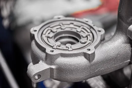
Bore capacity, power rating, and torque capacity are the three headline numbers on any fluid-coupling datasheet. A typical industrial unit is rated up to 177 mm (7 in) bore, 1,119 kW (1,500 hp), and 7,367 Nm (66,000 in-lb) torque [S7]. For very large drives, variable-speed fluid couplings cover 100 kW to 35 MW for pumps, fans, and compressors [S2].
For conveyor duty, total system inertia (not just motor nameplate kW) is the better sizing input; the coupling's slip characteristic must be matched to the inertia ratio so that the start ramp matches the belt stretch behaviour and the motor does not stall [S5]. A common dealer checklist: confirm the coupling's rated kW is at least motor kW multiplied by the driven-machine service factor; confirm the slip at full load is within 2-5%; and confirm the thermal rating (kW of heat dissipation) for the ambient temperature [S4].
Failure Modes Engineers See in the Field
Three failure patterns dominate service tickets on automotive plant fluid couplings. (1) Overheating from under-rated kW or restricted ventilation, which hardens seals and degrades the hydraulic oil [S4]. (2) Gearbox wear from insufficient torque cushioning, where the wrong coupling lets torsional shocks through to gear teeth [S4]. (3) Unplanned shutdowns from load-mismatch at start-up, where the coupling is either too stiff (stalls the motor) or too soft (never reaches running speed) [S4].
For paint-shop conveyors and other applications with both high inertia and variable load, simulation software is now standard for selecting coupling size and fill volume, rather than relying on nameplate kW alone [S5]. This mirrors the broader shift in automotive line engineering towards model-based drivetrain sizing, the same logic behind digital-thread line planning as covered in digital twin decision frameworks for 2026 plants.
Coupling Family vs Load Type: A Quick Comparison
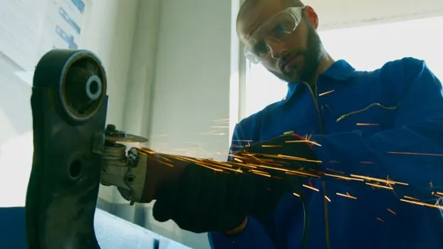
Fluid couplings belong to a wider family of power-transmission couplings, and the right family depends on the duty cycle. For soft-start heavy inertia in an automotive line, a shaft coupling without slip will not protect the gearbox the way a fluid coupling will, and a coupling-clutch combination is a different solution aimed at frequent engage/disengage cycles rather than continuous slip [S3].
The complete hydrodynamic fluid coupling category includes the constant-fill type (simple, maintenance-light, suited to fans and pumps) and the fill-controlled type (higher power density, suited to long conveyors and shock-loaded presses) [S5]. For automotive plants, the practical rule is: constant-fill for body shop transfer conveyors running steady, fill-controlled for paint-shop and assembly lines with variable load and high starting inertia.
Maintenance and Operating Signals to Track
Track three numbers on each installed fluid coupling: oil temperature at the housing (steady-state target below 90 deg C for mineral oil), oil level (constant-fill units lose oil only through seal leakage; a falling level means a seal problem, not a topping-up job), and slip percentage measured at the input and output shafts (rising slip at constant load signals internal wear or under-fill) [S4][S6]. The slip-versus-load curve is the most direct health indicator: a new coupling's slip at full load is 2-5%; if it climbs past 8%, the unit is degrading [S6].
Two signals worth watching on 2026 automotive lines: (1) growing use of simulation-driven coupling selection rather than catalogue kW matching, driven by the wider move to model-based line engineering [S5]; (2) tighter thermal management around couplings in paint-shop booths, where ambient temperature and limited ventilation push couplings closer to their thermal derating curve, see also PLC scan-time budgeting for the wider controls-side response on these lines.