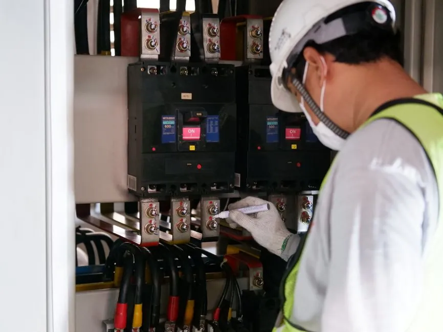
An inductive proximity sensor specified as "flush" can be embedded directly into a metal bracket with its face level to the surface; a "non-flush" (also called non-shielded) unit of the same diameter reaches roughly 1.5 to 2 times the operating distance but requires a metal-free clearance around the head [S4][S5].
The trade-off is the central decision a controls engineer makes when populating a sensor I/O list, and the wrong choice is one of the most common sources of false triggers, missed counts, and field retrofits on automated cells [S1][S3].
How the Two Mounting Types Differ Internally
Both units use a wound coil to build an electromagnetic field, but the field geometry is set by the housing. A flush-mount sensor has a metal ring (or internal shielding pot) around the coil that channels the field forward through the face only, which is what lets it sit in a steel bracket without the bracket being detected as a target [S4][S8].
A non-flush sensor has no such collar, so the field radiates both forward and laterally, producing a larger dome-shaped sensing region [S3][S4]. The metal ring also has a manufacturing cost: flush sensors reach only about 60% of the rated operating distance of an equivalent non-flush unit of the same housing diameter, and engineers compensate by stepping up one housing size when range is critical [S5].
Operating-Distance Numbers Across Common Diameters
Pepperl+Fuchs publishes reference operating distances for cylindrical inductive sensors that put the flush vs non-flush gap in concrete numbers. For an M12 housing, flush mount gives 2 mm while non-flush gives 4 mm, a 2x ratio; for M18 the values are 5 mm vs 8 mm; for M30, 10 mm vs 15 mm, plus a third "extended" column at 6 mm / 12 mm / 22 mm respectively for semi-flush families [S5].
GTRIC's published product-line envelope goes further, listing flush sensing ranges of 1 to 20 mm against 2 to 40 mm for the non-flush family of the same form factor, consistent with the 1.5 to 2x multiplier [S4]. M8 in flush is rated 1.5 mm; in non-flush it is 2 mm standard or 3 mm extended [S5].
Required Free Zone and Sensor-to-Sensor Spacing

Non-flush sensors are the harder of the two to install because of the free-zone rules. Pepperl+Fuchs specifies a free diameter "B" of 3 times the housing diameter around the head, a free height "A" of 2 times the operating distance in front, and a minimum sensor-to-sensor pitch "F" that depends on whether the neighbour is flush or non-flush; mounting a non-flush sensor in metal produces attenuation or false triggering [S1][S5].
Flush sensors by contrast can be set with A = 0 mm in metal, which is the reason the body is mechanically protected, less sensitive to debris, and less prone to lateral interference on dense fixture plates [S1][S3][S5]. Semi-flush (extended-range) sensors split the difference: they cannot sit fully embedded but only need a small protrusion defined as A = 0.2 x diameter in ferromagnetic material, or A = 0.1 x diameter in non-ferromagnetic, or A = 0 in non-conductive material [S5].
Decision Matrix: Which Type Goes on the Drawing
For new panel designs in automotive cells, food-grade conveyors, or any location with weld spatter, washdown, or operator contact, default to flush: it is recessed, EMI-tolerant against neighbouring sensors, and tolerant of bracket material [S3][S5]. For long-reach applications such as detecting a target across a gap, a non-flush is the right call, with the free-zone and bracket rules written into the mechanical drawing before the sensor cutout is placed [S1][S4].
Where the target distance is between the two, semi-flush (extended-range) sensors close the gap with only a small protrusion, useful when the bracket is aluminium or plastic and the operating distance needs to clear 12 mm on an M18 or 22 mm on an M30 [S5]. Balluff's catalog adds a third practical axis, mounting in non-conductive material: a non-flush sensor can be embedded fully flush in plastic or aluminium without false triggering, while the same sensor in steel needs the free zone, and many field mistakes come from ignoring that material-dependent rule [S2][S8].
Failure Modes and Field Mistakes to Engineer Out
Predamping (the sensor permanently detecting the surrounding metal as if a target were present) is the failure mode of a non-flush sensor installed in a steel bracket too close to the head, and it manifests as the output being stuck ON even with no target in front of the face [S1][S3].
Mutual interference is the second common failure: two non-flush sensors mounted too close to each other cross-fire because their lateral fields overlap, producing phantom triggers; flush sensors, with their suppressed lateral field, are far less susceptible to this, and a small minimum pitch F is sufficient [S3][S5]. Mechanical damage is the third: a non-flush sensor that protrudes from the bracket is more exposed to impact and accumulated contamination, which is why many plants in stamping or heavy-industry cells standardise on flush even at the cost of stepping up one housing size [S3].
Side-by-Side Criteria Comparison
Read across the two columns for a quick select: Electromagnetic shielding is present on flush, absent on non-flush; sensing distance is shorter on flush, 1.5 to 2x longer on non-flush for the same diameter; metal-free zone is minimal or none for flush, typically 3x sensor diameter on non-flush; mountable flush in metal bracket is fully safe for flush, forbidden for non-flush; lateral field radiation is suppressed on flush, significant on non-flush; EMI immunity from adjacent sensors is higher on flush, lower on non-flush; mechanical protection is better on flush (recessed), more exposed on non-flush; switching frequency tends to be higher for flush in the same housing, and typical sensing-distance envelopes are 1 to 20 mm (flush) against 2 to 40 mm (non-flush) across the common M8 to M30 cylindrical families [S4][S5].
For a deeper dive on how shielded inductive sensors interact with adjacent capacitive and photoelectric devices on the same bracket, the inductive sensor reference covers the coil-and-core fundamentals behind these rules. The same free-zone logic that drives non-flush inductive mounting also drives capacitive sensor head placement, and a controls engineer should treat both with the same bracket-and-clearance drawing discipline.
Selection Rule of Thumb and Sourcing

Pick flush by default and step up one housing size when the operating distance runs short; pick non-flush only when the extra 40 to 100% range is mandatory and the bracket is non-conductive, non-ferromagnetic, or has been machined with the full 3x-diameter free zone [S4][S5].
For wider context on how a shielded inductive sensor compares against a proximity probe or a displacement sensor for sub-millimetre analogue position feedback, the related selection guide 2D vs 3D vision for robot guidance: 2026 selection matrix covers the camera-side decision; if the upstream question is a digital I/O count vs a vision cell, weigh the sensor cost against the targeted use case, since 2026 panel-builder catalogues continue to rate inductive units in the tens of dollars per point where a vision system runs in the thousands [S4].