
A well-tuned 2D area-scan system can locate a flat, well-lit part with repeatability under 0.1 mm in production, and it does so at a fraction of the integration cost of a 3D sensor stack [S3]. The same 2D camera, however, returns no Z value and breaks down the moment parts arrive stacked, tilted, or with variable height.
3D vision, built on structured light, laser triangulation, stereo, or time-of-flight (ToF) imaging, adds the missing depth axis and is what unlocks bin picking, depalletizing of mixed loads, and any application where the robot must adapt to a pose it did not expect [S3][S4]. This guide lines the two up criterion by criterion so a process engineer can pick without re-reading ten vendor blogs.
Where 2D Vision Is the Right Tool
2D machine vision captures a flat image and analyzes X, Y position plus in-plane rotation (Rz) only, which is enough when parts are presented on a single plane in a known orientation [S1][S6]. A mature 2D cell running controlled LED or dome lighting is widely used for printed circuit board inspection, label verification, optical character recognition, and barcode reading, tasks where contrast and color carry the information rather than geometry [S1].
Cost and integration effort are the second-order reasons 2D still wins most retrofits. Photoneo and Mech-Mind both note that 2D systems are less expensive to integrate, compatible with a broader range of off-the-shelf software packages, and treated as the default technology for the majority of machine vision system cells [S1][S4]. A 2D area-scan camera running pattern matching on a stable conveyor typically reaches cycle times a 3D point-cloud pipeline cannot match, because the image-processing burden is one frame of pixels rather than a depth map plus color overlay [S3].
Where 2D Breaks Down
2D has four hard failure modes an engineer has to plan for. First, it can identify flat parts clearly only when they are separately arranged in a plane, so anything stacked demands a feeder or shaker table that adds hardware cost [S4]. Second, a 3D-shaped part looks completely different at different angles, and 2D vision has no orientation cue beyond Rz, so the same part on a different face is effectively a new pattern [S4].
Third, there is no depth information at all, so bin walls, overlapping objects, and varying part height all become noise rather than signal [S4]. Fourth, 2D is highly lighting-dependent: a shift in ambient illumination re-contours edges and triggers false rejects, which is why dome, backlight, or coaxial vision light source hardware is treated as part of the cell rather than an accessory [S1][S3]. Photoneo sums the constraint as 2D requiring highly controlled environments with standardized viewpoints and meticulously calibrated lighting [S1].
What 3D Vision Adds
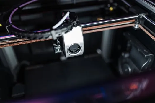
3D machine vision systems capture three-dimensional data, including distance and volume, using structured light, laser triangulation, stereo vision, or ToF sensors, and produce a full point cloud or depth map of the scene [S1][S5]. The payoff is that the robot receives X, Y, Z plus full Rx, Ry, Rz orientation, which is what bin picking, depalletizing, and large-pose-variance assembly actually need [S3][S5].
3D is also largely immune to the contrast and ambient-light sensitivity that plagues 2D, because depth is recovered from projected patterns or triangulation rather than from surface shading [S4]. Mech-Mind's framing is direct: 3D vision, unlike 2D systems, is not derailed by distance, contrast, or lighting variation in the way 2D is [S4]. The trade-off is computational load, since a 3D pipeline has to reconstruct geometry and then run matching on it, and that load is the reason real-time 3D cells pair the sensor with a dedicated vision controller or an industrial PC rather than a PLC [S3].
Decision Matrix: 2D vs 3D on the Criteria That Matter
The table below condenses the public guidance into the four criteria a 2026 spec review actually scores on. Numbers are stated only where the research supplied them; otherwise the comparison is qualitative. [S3]
Accuracy and repeatability: 2D systems can reach under 0.1 mm repeatability on flat, well-lit parts [S3]; 3D systems trade some of that raw repeatability for the ability to resolve height, so they are specified when pose variability, not sub-tenths precision, is the bottleneck [S3][S5]. Cost and integration effort: 2D is consistently described as the lower-cost, lower-effort default [S1][S4]; 3D carries a higher sensor price and a heavier calibration burden because hand-eye alignment errors propagate into Z as well as X and Y [S3]. Lighting and environment tolerance: 2D demands controlled lighting and stable backgrounds [S1]; 3D is largely tolerant of ambient variation because the projected pattern or triangulation baseline carries the geometry [S4]. Part geometry fit: 2D is correct for flat, single-plane, fixed-orientation parts; 3D is required for stacked, overlapping, or randomly posed parts where depth is a decision input [S3][S4][S5].
Matching the System to the Application
Pick 2D when the cell presents parts on a flat surface in a known orientation, when the inspection target is surface or label quality, or when cycle time on a moving conveyor is the limiting constraint [S1][S3][S6]. A 2D area-scan camera plus a vision imaging pipeline is also the right answer for reading, OCR, code verification, and any purely two-dimensional metrology job.
Pick 3D when parts arrive in bins, totes, or mixed-SKU pallets, when the robot has to grasp a feature that depends on full 6-DoF pose, or when the application is welding, dispensing, or assembly where a varying Z height would otherwise crash the end-effector [S3][S4][S5]. For very small parts where the field of view has to be sized to a few centimeters, the 3D scanner selection drives the optics rather than the algorithm, and the same depth-sensing trade-offs apply. A 3D cell is also the practical answer for any task described as machine-vision identification of parts whose identity depends on shape, where 2D pattern matching cannot separate look-alike SKUs reliably [S5].
Integration Reality: Protocols, Latency, and Calibration
Whichever system is chosen, the vision-to-robot link has to clear three engineering bars. First, protocol: common industrial links are Ethernet/IP, PROFINET, EtherCAT, and direct serial, and the choice of fieldbus has more impact on latency than most spec sheets admit, which is one reason plants keep standardizing on PROFINET while machine builders keep picking EtherCAT for cell-level motion [S3]. Second, latency: a vision system returning X, Y, Z plus Rx, Ry, Rz on a high-speed pick-and-place line has to deliver that pose inside the conveyor's travel window, or the robot reaches for a part that has already moved [S3].
Third, calibration: the hand-eye transform between camera frame and robot frame is the single biggest source of placement error in a vision-guided cell, and errors in calibration propagate directly into placement accuracy, especially in Z where a 3D sensor magnifies the mistake [S3]. The other underestimated variable is the machine vision ID stack, which still has to be trained on enough part variants to cover real production mix, otherwise the cell rejects good parts at the gate.
Failure Modes and Limits an Engineer Has to Plan Around

2D fails when lighting drifts, when parts shadow each other, when a part presents its unknown face to the camera, or when Z is part of the answer [S1][S4]. 3D fails when the part is highly reflective or transparent, when the scene is outside the sensor's standoff or field of view, when the point cloud is too sparse for the feature being grasped, or when the compute budget cannot keep up with the cycle time [S3][S5]. ToF sensors in particular struggle with multi-path interference in cluttered bin interiors, which is why structured light and laser triangulation are still preferred for high-precision bin picking despite their heavier processing load [S5].
A practical guardrail is to spec the 3D sensor's depth accuracy and point density at the working distance actually used in the cell, not at the headline lab number, because real shop-floor lighting and part reflectivity erode both [S3]. Photoneo's framing is the right test: 3D is not a replacement for 2D, it is a separate tool that earns its place only when depth is a real input to the decision [S1].
The next decision node, once 2D versus 3D is settled, is field of view and working-distance sizing for the chosen sensor class, and the cycle-time handshake between vision pose update and robot motion-blend time on the chosen fieldbus, both of which are trackable signals for any 2026 cell retrofit.
See also our earlier report, Field gateway vs cloud IoT gateway: spec-driven selection for edge data aggregation.