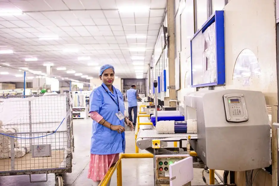
Textile mills running ring spinning, weaving looms, carding machines, and finishing range drives need gear couplings that handle continuous torque with shock peaks, tolerate up to ±2° angular and 0.7–1.3 mm parallel misalignment, and survive lint-laden, humid environments above 30 °C ambient [S1][S5].
The selection logic below is the same procedure textile plant engineers use today: derive a design torque (or design kW) from motor nameplate × service factor, then match the resulting kW/rpm point to a coupling size on the manufacturer chart, with a 3800–20000 h life factor built in [S5].
Why Textile Drives Are a Distinct Sub-Case of Heavy-Duty Coupling Sizing
Textile drives sit between light-duty and true heavy-duty (steel-mill, crusher) coupling service: continuous torque with high cyclic shock on looms, but ambient is humid, lint-loaded, and often above 30 °C, not the abrasive dust of a rolling mill [S2]. The GF-series reference data shows torque ratings from 11 Nm (GF-14) to 410 Nm (GF-65) with maximum speeds of 14,000 rpm down to 4000 rpm, and a 3800 h baseline life that scales to 20000 h with factor f2 = 1.58 [S5]. This bracket covers most spinning frames, winders, draw frames, and small card drives. For larger finishing ranges, mills move to industrial gear couplings with capacities well into the kNm range, identical in selection logic but with lubrication ports added for the higher continuous load [S3].
The coupling must never see a peak motor torque above twice its rated torque, per the published rule for the GF family [S5]. The same two-times rule is applied by most mill-grade gear coupling suppliers [S1].
Sizing Procedure: kW/rpm, Service Factors, and the Two-Times Torque Cap
Selection begins with design power Pd = P × f1 × f2 × f3 (kW) or design torque Td = T × f1 × f2 × f3 (Nm), where f1 is the application service factor, f2 is a life factor (1.0 at 3800 h rising to 1.58 at 20000 h), and f3 = 1.12 when angular misalignment is close to the catalogue limit of 5 minutes of arc [S5]. Divide Pd by shaft speed to get kW/rpm, then read the coupling size on the chart that meets or exceeds that value at the operating rpm [S5]. The published GF table lists power capacity at 1000, 1500, and 3000 rpm; the 3000 rpm column is the relevant row for most 4-pole 50/60 Hz textile motors.
For example, a 7.5 kW motor at 1500 rpm requires a design point of at least 7.5 kW/1500 rpm = 0.0050 kW/(r/min), and on the GF table, GF-32 (7.2 kW at 1500 rpm, 69 Nm) is the smallest standard size that meets the bare requirement, but with service factor f1 = 1.5 for a loom, the spec jumps to GF-38 (88 Nm, 9.2 kW at 1500 rpm) [S5].
Misalignment Capability Specific to Spinning and Weaving Frames
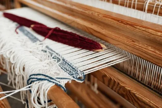
Textile frames, especially long spinning lines with multiple motor stations, develop parallel offset from foundation settling and angular misalignment from belt or chain tensioning misalignment. The GF family is rated at ±2° angular and 0.7–1.3 mm parallel (radial) misalignment across its ten sizes, with axial travel of ±1 mm [S5]. Industrial gear couplings used in larger textile plants are commonly rated at up to ±0.5° angular per hub and several millimetres of parallel offset, depending on size [S2][S3].
For frames where shafts are widely separated, a floating-shaft or spacer gear coupling is the conventional choice, providing the additional DBSE (distance between shaft ends) needed for maintenance access [S1].
Coupling Type vs Textile Application: Comparison Matrix
The table below aligns the four common gear-coupling architectures against textile-mill criteria. Values are drawn from the source references and reflect typical published ratings, not single-vendor claims. [S2]
Full gear coupling (both hubs flexible): highest torque capacity, handles angular + parallel + axial, fits main drive shafts on carding and ring-spinning frames; requires regular grease lubrication [S1].
Half gear / half rigid coupling: one rigid half saves cost and axial length, used on short shaft-to-shaft sections like individual motor-to-gearbox couplings where misalignment is small [S2].
Floating shaft (spacer) gear coupling: covers large DBSE on long spinning lines and between finishing-range sections, allows shaft removal without disturbing alignment of connected machines [S1].
Continuous sleeve gear coupling (GF type): compact, polyamide sleeve impregnated with solid lubricant, –20 °C to +80 °C continuous (120 °C short duration), fits lower-power individual drive sections up to 410 Nm / 14,000 rpm, maintenance-free for the sleeve life [S5].
On cost-per-kW and maintenance burden, the continuous-sleeve design wins below ~50 Nm; above that, the full gear coupling with grease ports is the more durable textile-mill default [S5].
Bore, Keyway, and Fitment Tolerances for Mill Retrofits
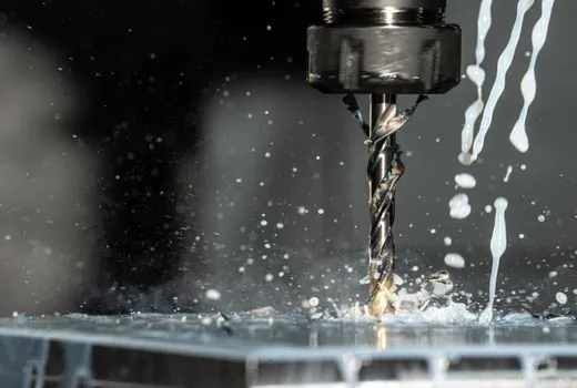
Bore-to-shaft mismatch as small as 0.05–0.1 mm causes sliding, fretting, and overheating on textile motors that already run near their thermal limit [S2]. Specify finish-bored hubs with keyway to ISO or DIN tolerances rather than pilot bore whenever the shaft is finished, and use interference fit (H7/r6 class is common) for high-torque sections; clearance fit is reserved for positions requiring frequent removal [S2][S5].
Keyway width and depth tolerance must be held to within ±0.05 mm on looms, where reversing torques during pick operation work the key repeatedly [S2].
Materials, Lubrication, and the Lint/Humidity Risk Factor
Standard mill-duty gear couplings use medium-carbon alloy steel hubs (through-hardened or case-hardened to ~58–62 HRC on the tooth flank) with phosphated or zinc-plated external surfaces for corrosion resistance [S1][S5]. For the sleeve half of a GF-type continuous-sleeve coupling, the material is high-molecular-weight polyamide impregnated with solid lubricant, which removes the need for relubrication in low-power sections [S5].
For full gear couplings in humid textile halls, specify food-grade or synthetic grease with a dropping point above 180 °C and a base oil viscosity of ISO VG 220 to 460; relubrication interval drops by roughly 30 % versus a dry-steel-mill environment due to lint contamination [S3].
Speed Limits and Balance Class for High-RPM Spindle Drives
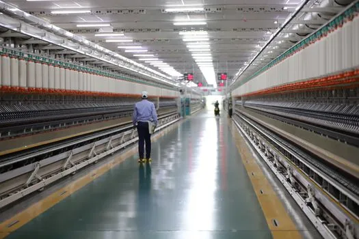
Published maximum speeds for the GF family are 14,000 rpm at the smallest size (GF-14) decreasing to 4000 rpm at GF-65, and couplings must be dynamically balanced when the running speed exceeds the coupling's first resonance, typically above ~3000 rpm for textile frame sizes [S5]. Exceeding the speed rating leads to tooth wear, vibration, and catastrophic failure [S3].
For ring-spinning and doubling spindles running 8000–15000 rpm, the continuous-sleeve GF design is the standard fit; for slower main carding drives at 1500–3000 rpm, the industrial full gear coupling with grease lubrication is the more common choice [S5].
Selection Checklist for a Textile Mill Purchase Order
Confirm motor kW and full-load rpm, peak torque (especially for looms), DBSE, and ambient temperature. Calculate Pd = P × f1 × f2 × f3 and read kW/rpm off the chosen coupling's capacity table; verify the two-times torque rule and the 3800–20000 h life target [S5].
Specify bore tolerance, keyway standard, lubrication grade and interval, sleeve material, balance class, and any required ATEX or IECEx certification for dust zones (carding, blowing rooms). Cross-check the chosen size against an industrial gear coupling reference and the related gear reducer selection page when the coupling sits between motor and reducer. For mixed-fleet plants standardising on one product line, align the spec to a helical gear reducer family so the coupling bore stack matches the reducer input shaft.
Trackable signals: (1) the OEM's published kW/rpm table at the operating rpm column, (2) the 2× peak-torque rule applied to the actual loom drive cycle, and (3) the relubrication interval stated in hours, adjusted for the lint/humidity derating above. For broader driveline context beyond couplings, a textile plant standardising on gear-type power transmission can cross-reference gear pump selection where hydraulic or lube-oil circulation shares the same driveline, and a coupling-and-clutch assembly note for combined start-stop service. Plants running a mix of textile and metal-cutting equipment can adapt the same logic from the related automotive production-line spec map for higher-torque stations.