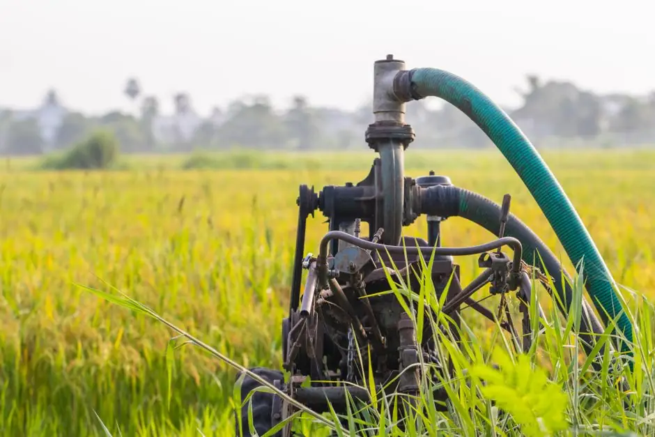
A correctly installed external or internal gear pump delivers a fixed displacement per revolution, with flow equal to displacement multiplied by shaft speed, independent of discharge pressure within the rated envelope [S4]. Installation errors, not pump defects, drive most early-life failures documented in 2026 field-service guides [S1][S2].
Positive-displacement gear pumps build pressure until something relieves it, so a properly sized pressure relief valve is non-negotiable on every install [S1]. The six steps covered below, mechanical mounting, alignment, priming, fluid cleanliness, hose routing, and commissioning checks, map directly to the failure modes that scrap pumps in the first 90 days of service [S1][S2][S3][S6].
Pre-Install Inspection and Mounting Geometry
Verify mounting flange, shaft type, rotation direction, and port orientation against the OEM data plate before any bolt is turned; a technically correct pump can still fail if the physical fit to the host machine is wrong [S4]. For dump-truck and mobile installs, confirm the pump model flow, rotation, and pressure rating against the PTO output speed, mounting pad, and reservoir volume before shimming the bracket [S3].
Measure distance to crossmembers, exhaust, and suspension parts so the pump has clearance for hose bend radius, service access, and driveshaft guard clearance [S3]. A straightedge across the PTO and pump flanges plus feeler gauges on the gap is the minimum alignment evidence; record the readings, a shim-only correction that tilts or twists the housing still produces side loads on the shaft [S3].
Torque mounting bolts in a cross pattern to the chart value for the bolt grade, apply thread locker only where the maker permits it, then spin the shaft by hand to confirm no binding before coupling the motor [S3]. Re-torque after the first work shift, mobile hydraulic mounts routinely settle 0.1 to 0.3 mm under vibration and the resulting misalignment shortens bearing life faster than any other install defect [S2][S3].
Shaft Alignment Between Motor and Pump
Shaft misalignment is the most common bearing-killer in motor-driven gear-pump skids, and it is fully preventable with a dial indicator or laser alignment check at install [S2]. Both angular and parallel misalignment must be inside the coupling maker's tolerance, typically below 0.05 mm parallel and below 0.05 mm/100 mm angular for close-coupled flexible couplings.
Wrong rotation reverses suction and discharge ports, so the rotation arrow on the pump housing must be confirmed against the motor's wired phase order before the coupling is connected [S1][S2]. For belt- or PTO-driven installs, driveshaft angles and u-joint phasing control the side-load on the pump shaft; the working angle should stay below 5 degrees for continuous-duty mobile service [S3][S5].
For pumps driven by a truck power take-off, alignment is set by the PTO pad and the pump flange sitting in the same plane; a PTO pump that is too small causes slow cylinder lift, while an oversized pump generates heat and stresses the relief circuit on every cycle [S5]. Confirm PTO output speed, shaft, flange, and rotation against the pump nameplate before lifting the pump onto the mount [S5].
Priming, Suction Line, and Fluid Cleanliness
Gear-pump priming means displacing air from the pump housing and inlet line so the gears move fluid rather than compress air, and the standard field sequence runs through six steps: inspect, fill the reservoir, fill the pump housing, bleed the suction line, jog the motor, and verify flow [S2]. Skipping the priming step is the number-one cause of early hydraulic-pump failure, because the gear teeth and housing walls run metal-on-metal without an oil film [S2].
Most gear-pump hydraulic systems need fluid at ISO 4406 18/16/13 cleanliness or better, and new fluid straight from a drum often exceeds that particle count and must be filtered before it enters the reservoir [S2]. The table below lines up the four damage modes that a missed prime leaves behind, which doubles as the rationale for the priming step:
Failure mode and root cause: gear scoring from metal-on-metal contact with no lubrication, seal blowout from pressure spikes caused by trapped air, cavitation erosion from air-vapor bubble collapse, and bearing failure from loss of the hydrodynamic oil film. Typical time to failure ranges from seconds to minutes for gear scoring, minutes to hours for seal blowout, hours to days for bearing failure, and days to weeks for cavitation erosion [S2].
Open the suction valve fully during commissioning, because a partially closed suction valve creates a restriction that causes cavitation and is one of the most common post-install complaints [S1]. A fine-mesh screen funnel and lint-free rags are not optional; a single particle of lint can score a gear flank in the first hour of run-in [S2].
Hose Routing, Fittings, and Relief-Valve Sizing
Hydraulic hose routing should follow SAE J1273 practice: keep bend radius above the manufacturer minimum, avoid sharp edges, isolate from heat sources and moving suspension parts, and support long runs with clamps to prevent chafing [S3]. For log-splitter and similar mobile circuits, the outlet port thread type matters as much as the hose size; a male NPT port requires NPT fittings, because a straight-thread O-ring boss fitting will not seat and can damage the port [S7].
Reservoir return filtration and suction-line sizing are the two plumbing decisions that determine whether the pump lives or dies from cavitation. Suction lines should be one or two pipe sizes larger than the pump inlet port, with as few elbows as the physical package allows, and a flooded suction (reservoir above pump centerline) is strongly preferred for cold-start and high-speed service [S1][S2].
Pressure-side fittings must be rated to the pump's maximum pressure, not the nominal working pressure; a pump rated at 250 bar continuous and 280 bar peak needs fittings rated to 280 bar or higher with a safety margin for surge [S1][S3]. Mixing mineral oil with a synthetic or fire-resistant fluid is a common commissioning mistake that produces seal swelling, additive dropout, and sludge formation within hours of run-in [S2].
Commissioning Checks and Acceptance Criteria
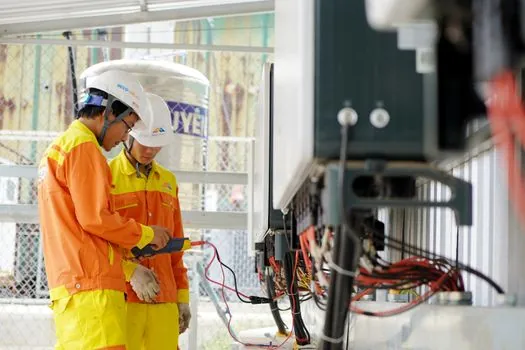
On first start, monitor the discharge pressure gauge immediately; pressure should stabilize within seconds, and any slow climb past 10 seconds indicates air in the housing or a partially blocked suction line [S1]. Listen for knocking, grinding, or screaming sounds in the first 60 seconds, because these are the early-warning signs of cavitation, bearing failure, or a dry-running gear set [S1].
Acceptance values for a healthy first-hour run include: stable discharge pressure within plus or minus 5 percent of setpoint, suction vacuum below the pump maker's NPSH-R margin, fluid temperature rise below 8 to 10 degrees Celsius over ambient, and no more than a 2 to 3 degrees Celsius rise across the pump housing [S1][S2]. Log the readings against the install record; trends matter more than absolute values, and a slow upward drift on housing temperature over weeks signals bearing wear long before failure [S1].
When troubleshooting no-flow conditions on a pump that has been in service, work the same six priming steps before condemning the pump: inspect, fill the reservoir, fill the pump housing, bleed the suction line, jog the motor, and verify flow [S2]. A pump that primes correctly, holds discharge pressure, but delivers reduced flow almost always points to internal wear, a partially blocked filter, or a relief valve stuck open, not to an install defect [S1][S2].
When to Stop and Escalate Instead of Repairing
Do not attempt to repair a pump that has run dry for more than a few seconds; gear scoring, heat-expanded housings, and compromised bearings mean a single dry-run incident can require complete pump replacement [S1]. Visible metal-flake debris in the reservoir, scored gear flanks, or a discolored housing (blue, bronze, or rainbow temper colors) are replacement triggers, not repair triggers [S1][S2].
Escalate to the OEM or a qualified service shop when commissioning pressure will not stabilize within 30 seconds after a clean prime, when suction vacuum exceeds the published NPSH-R curve by more than 10 percent, or when housing temperature continues to rise after the first 10 minutes of no-load run [S1][S2]. For mobile hydraulic systems covered by SAE J1273 hose practice and ISO 4406 cleanliness targets, the install is not accepted until both the pressure test and the cleanliness sample are recorded [S2][S3].
Trackable next signals: monitor the 90-day bearing-temperature trend and the 6-month fluid-cleanliness sample against ISO 4406 18/16/13; rebuild intervals for gear-pump bearings and seals commonly fall between 4,000 and 8,000 hours for industrial duty and 2,000 to 4,000 hours for mobile duty, so the first scheduled teardown should be planned inside those windows, not after a failure [S1][S2]. For an at-a-glance look at the gear-pump family and the gear pump types covered in the field guides above, including external, internal, and gerotor variants, see the 2026 spec map.
Spec-level background on the components involved: linear guide, and crossed roller guide.
See also our earlier report, Gear Pump Types and Classifications: A 2026 Spec Map.