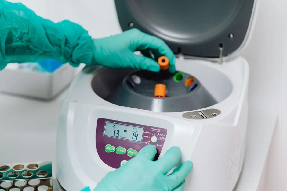
A centrifugal pump is a dynamic (non-positive-displacement) flow machine that moves fluid by converting the kinetic energy of a rotating impeller into pressure energy inside a volute or diffuser casing, with single-stage heads from a few metres and multistage designs exceeding 1,000 m of delivery head [S1][S5].
They dominate industrial fluid transfer because they handle low-viscosity liquids, water, light oils, dilute chemicals, with continuous, non-pulsating flow at high volume, but they are not self-priming, lose efficiency rapidly as viscosity rises, and are vulnerable to cavitation when Net Positive Suction Head (NPSH) available drops below NPSH required [S1][S2][S5].
Working Principle and Core Components
A motor-driven shaft spins an impeller with curved vanes inside a stationary casing, generating centrifugal force that flings fluid outward and creates a low-pressure zone at the impeller eye; atmospheric or supply pressure then pushes more liquid up the suction pipe, and the volute (a spiral casing) or diffuser (staged guide vanes) decelerates the high-velocity discharge to convert kinetic energy into pressure per the Bernoulli principle [S1][S2][S4]. The five functional components common to every unit are the impeller, casing, shaft, bearings, and seal arrangement (mechanical seal or gland packing), with suction and discharge nozzles completing the flow path [S1][S5]. Open, semi-open, and closed impeller geometries are chosen based on fluid cleanliness and solids content, and seals are commonly specified in silicon carbide faces for abrasive or high-temperature service [S5][S9].
Selection Criteria: Head, Flow, NPSH, and Viscosity
Specifying a centrifugal pump is a four-variable problem: required head (m), required flow (m³/h), NPSH available at site versus NPSHr of the candidate, and fluid viscosity at the operating temperature [S1][S5]. Multistage configurations stack impellers in series to push delivery head above 1,000 m for boiler-feed and reverse-osmosis high-pressure service, while single-stage end-suction units are the default for general water transfer with delivery rates up to several thousand m³/h [S5]. Vertical sump designs save floor space for tank mounting, whereas horizontal configurations simplify maintenance access and are the common industrial-process default [S5][S8].
For fluid systems where flow must be metered at the pump discharge to close a mass-balance loop, an electromagnetic flowmeter is often paired with the centrifugal pump because both work on clean, conductive low-viscosity liquids without obstructing the flow path.
Advantages: Why Centrifugals Dominate Industrial Fluid Transfer

Centrifugal pumps ship with few moving parts (impeller, shaft, bearings), giving high mechanical reliability and lower maintenance cost than positive-displacement alternatives [S1][S2][S4]. Flow is smooth and continuous rather than pulsed, which protects downstream instruments, piping, and filters from fatigue loading [S1][S2]. They scale cleanly across duty points: a single horizontal end-suction frame can cover building-services HVAC, a vertical multistage can hit boiler-feed pressures, and an axial-flow variant can push very high flow at low head, all on the same operating principle [S1][S3][S5]. For continuous-duty applications such as cooling-water circulation, irrigation, and chemical transfer, the hydraulic efficiency of a properly selected centrifugal unit typically beats a positive-displacement pump of equivalent flow rating [S2][S3][S5].
Disadvantages: Cavitation, Viscosity, and Priming Limits
Cavitation is the dominant failure mode: when local pressure at the impeller eye falls below the fluid's vapour pressure, vapour bubbles form and then collapse violently in higher-pressure zones, generating microjets that can exceed 50 m/s and local pressures of several thousand bar, eroding impeller surfaces within hours [S7]. The same source quantifies bubble-collapse events at more than a hundred cycles per second, which is why NPSH margin is the single most-checked number on a centrifugal datasheet [S1][S7]. Centrifugals are also not self-priming: the suction casing must be flooded before start, or a separate priming system (vacuum pump, ejector, or self-priming stage) is required [S1][S2]. Viscosity above roughly 200-300 cSt starts to slash head and flow performance, and abrasive slurries accelerate mechanical-seal and impeller wear, pushing maintenance intervals down sharply [S1][S2][S5].
Comparison: Centrifugal vs Positive-Displacement and Other Dynamic Pumps
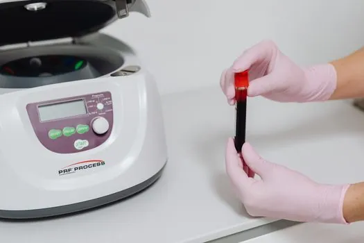
Selection against four decision criteria clarifies where a centrifugal fits and where it does not: (1) flow type: centrifugal gives smooth, continuous, non-pulsating flow, while diaphragm pumps and gear pumps deliver pulsed, metered, positive-displacement flow; (2) viscosity tolerance: positive-displacement designs handle viscous and shear-sensitive fluids better, whereas centrifugals are tuned for low-viscosity, water-like service; (3) self-priming: most centrifugals require flooded suction or an auxiliary priming device, while diaphragm and many gear designs are inherently self-priming; (4) pressure per stage: a single centrifugal stage tops out at moderate head, while positive-displacement units and multistage centrifugal stacks trade speed for pressure. The fundamental reference architecture of the centrifugal pump category is laid out in the centrifugal pump encyclopedia entry, which defines impeller, volute, and shaft geometry against hydraulic institute conventions. [S1]
Application Map and Materials of Construction
Centrifugal pumps cover the full industrial breadth: municipal water supply and distribution, HVAC chilled- and hot-water circulation, agricultural irrigation, oil-and-gas crude and refined-product transfer, chemical processing of corrosive fluids, power-plant cooling-water and boiler-feed service, and municipal wastewater handling [S1][S3][S4]. Materials of construction scale with the fluid: cast iron for clean water, stainless steel (including 316L for sanitary duties) for chemicals and food-grade liquids, and engineered plastics or rubber-lined casings for corrosive or abrasive media [S5][S9]. For regulated sanitary or food-and-beverage service, equipment is commonly specified to comply with hygienic construction standards such as EHEDG and 3-A, with surface finish and seal geometry controlled accordingly [S9].
Failure Modes and Field-Trackable Signals
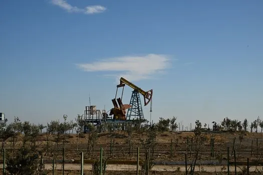
Beyond cavitation, three failure signatures show up repeatedly in service: mechanical-seal leakage traced to dry running or shaft misalignment, bearing failure from contamination or lubrication breakdown, and impeller erosion from solids or corrosive attack that degrades the pump curve over time [S1][S5]. The first diagnostic signal to log is a drop in discharge pressure at constant speed, which usually points to wear-ring clearance increase, impeller vane erosion, or air ingress on the suction side. The second is a rising motor current at unchanged flow, which flags a seized bearing, a partial impeller rub, or a process-fluid density increase. For plants managing dozens of rotating assets, a structured approach to the broader construction machinery and equipment base, including vibration monitoring and seal-flush plans, is where the centrifugal pump's reliability is won or lost in year two and beyond.
Track two signals over the next procurement cycle: published efficiency maps from major OEMs for ISO 5199 / API 610-compliant overhung and between-bearings designs, and the rollout of mechanical-seal cartridge standards that shorten mean-time-to-repair on fielded centrifugal units.