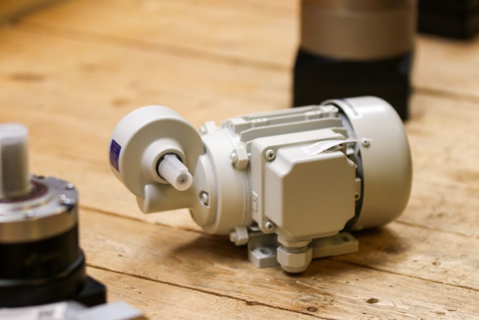
Industrial gearbox installation is governed less by brand choice and more by four mechanical checkpoints — mounting-surface flatness, bore/shaft tolerance class, interference-fit heating, and laser-aligned coupling — each tied to a published ISO or DIN clause [S3][S4]. Get those right and modern enclosed gear drives routinely cross 25,000-hour bearing life; get them wrong and gearmesh failure shows up inside the first 1,000 hours [S3].
This walk-through is written for the maintenance engineer or OEM builder who already has the gearbox on the floor and needs the spec numbers, not the marketing. Sources used are the Practical Maintenance "Fundamentals, Selection, Installation and Maintenance of Gearboxes" Part 2 reference, a ZF Duoplan 2K2100 two-speed manual, a Trico gearbox installation kit manual (Rev C, 01/26), and a Cipres flange-mounted gearbox IOM [S2][S3][S4][S6].
Foundation and Flange Flatness: DIN ISO 2768-2 Class H Is the Floor
Mounting-surface planeness must comply with DIN ISO 2768-2 class H on every contacting flange before any bolt is torqued, per the Cipres flange-mounted gearbox IOM [S4]. Contacting surfaces also have to be free of impurities and protected against rust — a contaminated or corroded face lifts local flatness out of class H even when the bare casting measures in. The bore that receives the output shaft must be produced to ISO 8015 with tolerance H7; the mating driven shaft inserted into a hollow output must be ISO 8015 h6 [S4]. An H7/h6 pair on a 50 mm shaft gives roughly 25 µm of clearance, which is the envelope that lets the bearing preload do its job without induced bending moment.
For hollow-output units, the input dimension called out by the ZF Duoplan 2K2100 manual is 39 ± 0.1 mm on the input shaft to allow bracing of the planetary gear carrier — a sub-0.1 mm stack-up that is invisible at the cast-iron face but fatal at the planet pins [S6]. Skim uneven flange faces with an oil stone before dry-fitting, not after the bolts have been pulled; the same ZF manual lists face-clean and skim inspection as the first three mechanical steps on a 2K2100 [S6].
Tools, Lifting, and Pre-Install Inventory
The Trico gearbox installation kit (61812 Rev C, 01/26) ships with a fixed tool list that doubles as a useful general checklist: 9/16, 11/16, 13/16, and 1-1/2 in open-end wrenches; a standard hex key set; a tubing bender for 3/8 in OD tubing; a tubing cutter; pipe sealant; a tape measure; and the gearbox OEM manual [S2]. Kits are sized by the sight-glass window in inches, and the breather and drain ports accept multi-component fittings with three 1/4 in NPTF connections on top and sides so the sight glass can be rotated to clear shrouds or cages [S2].
Lifting practice is non-negotiable: a gearbox must be rolled on bars or lifted through designated lugs, holes, or eye bolts, and you must use all available lifting points so load is shared — never lift a drive package by the gearbox's lugs alone, and never sling around a shaft extension [S3]. Slings or chains around the input or output shaft deform the seal area, and the Practical Maintenance reference treats that as a bearing-life event, not a cosmetic one. Heavy units also demand PPE — gloves, helmet, eye protection, steel-toed boots — and a clear, well-lit work area before any pinion or coupling hub is heated [S7].
Shaft Mounting, Interference Fits, and the 250–300°F Heat Window

Gears, pinions, sprockets, and sheaves with interference fits must be heated to between 250°F and 300°F (≈121–149°C) before being assembled to the shaft, and coupling hubs should sit flush with the shaft end unless the unit was specifically ordered for overhung mounting [S3]. That 50°F window is not a suggestion: below 250°F the hub does not fully expand and you scar the shaft; above 300°F you risk metallurgical change on case-hardened pinions. Mount the pinion or sheave as close to the gearbox housing as the casting allows — every extra millimetre of stand-off adds bending moment to the input shaft and shortens bearing life at a rate the OEM rarely prints on the nameplate [S3].
On units with a clamp-collar bore adapter (such as Teknic's NEMA-mount gearboxes), the access-port grommet has to be removed and the clamp collar rotated so the clamping screw lines up with the access port before the motor is mounted; otherwise the screw is buried under the motor face and you are left either disassembling or living with an under-torqued clamp [S5]. A parallel-key extractor or diagonal cutters should be on hand for key removal — forcing a key out with a screwdriver flats the keyway and turns a clean re-install into a shaft-replacement job [S5].
Alignment: Soft Foot, Hot, and Cold Targets
After foundation, the gearbox and driven equipment must be precisely aligned — typically by laser or dial indicator, with both angular and parallel offset checked at the coupling, then re-checked at operating temperature once thermal growth has equalised [S3][S4]. A "soft foot" check (feeler under each of the four feet) precedes any doweling or grouting; even 50 µm of soft foot on one corner will walk the gearbox sideways under load and turn a parallel misalignment into a coupling-failure event.
For hollow-shaft mounts with shrink discs or torque arms, the ZF 2K2100 instruction calls out a 39 ± 0.1 mm axial dimension specifically to control planetary carrier preload — that ±0.1 mm is a much tighter budget than most flange flatness calls, and it is the one number to re-measure after the final torque on the mounting bolts [S6]. Acceptance criteria in the Practical Maintenance reference are functional rather than numeric: full-load current within OEM nameplate, vibration velocity below 4.5 mm/s RMS on the housing, and oil temperature rise within the lubricant supplier's published curve [S3].
Lubrication Verification Before Energising

Verify lubricant type and quantity from the OEM manual before energising — never assume the factory fill is correct for the mounting orientation you just adopted, since breather and level-plug positions change with foot, flange, and shaft arrangements [S2]. Trico's kit procedure explicitly lists "Verify gearbox lubrication type and quantity needed" as step 3, immediately after inventory and before any port work, because once the multi-component fittings are sealed in with pipe sealant you do not want to be draining through an unfamiliar port [S2]. The kit's drain-side compression elbow, level-gauge sight glass, and breather-side fitting should all sit on the same side of the gearbox so the operator can read the level, sample the oil, and change the desiccant breather without crossing the coupling [S2].
For high-viscosity service, the same kit adds a quick-disconnect sampling port that ties into external filtration — a layout that maps well onto the condition-monitoring routines in the Practical Maintenance reference, which dedicates a full chapter to oil sampling and wear-debris trending on enclosed gear drives [S2][S3]. If your drive trains a slewing bearing downstream, the same bolt-up and run-out acceptance logic from slewing-ring installation applies to the slow-speed output flange.
Commissioning Checks and When to Walk Away from a Repair
Pre-energising checks: shaft turns freely by hand with no grinding or indexing feel, breather is unobstructed, oil level sits at the centre of the sight glass at rest, and the coupling guard is in place.
Replace, do not repair, when bearing-housing temperature rises more than 15°C above the bearing supplier's published curve, when oil-sample ICP shows >200 ppm iron or >50 ppm copper on a 1,000-hour trend, or when tooth-contact pattern sits outside the centred 60–80% flank length even after shimming [S3]. For vibration-trending baselines, the vibration analyzer buying guide and the proximity probe vs accelerometer decision map cover sensor selection; for the upstream motor side, the same installation discipline that protects a linear guide against contamination also protects a gearbox against the dust and water ingress that kills input seals. Trackable signal: confirm the OEM's foundation-drilling template against the as-built anchor pattern before the grout cures — retro drilling cured grout is the single most common cause of soft foot in field-rebuilt units [S3].
For component-level specifications, see crossed roller guide.