
Glass fiber reinforcement selection in chemical-service equipment (FRP tanks, ducts, scrubbers, piping to ASTM D3299 / D4097) is governed by five engineering gates — alkali class, filament diameter, sizing chemistry, matrix compatibility, and a chemical-resistance test per ASTM C581 or ISO 175 — and E-CR (electrical/corrosion-resistant) plus S-2 glass grades have become the default specification for acidic and mildly alkaline exposure [S1].
Misalignment at any of these five gates causes the failure mode the spec was meant to prevent: wicking along the filament, stress cracking at the resin–sizing interface, or catastrophic pH-driven leaching. The same glass-fiber family used in concrete abrasion trials (10% silica fume substitution, 5–15% fiber volume) confirms that mechanical performance still tracks back to the chemical bond at the fiber interface [S3].
Gate 1 — Alkali Class and Oxide Composition
Glass-fiber grade is set by its alkali-metal oxide content, and this single value drives both chemical durability and price. A-glass sits above 15% Na2O + K2O and is the cheapest grade; it dissolves rapidly in hot alkaline media. E-glass caps alkali content near 1% and is the workhorse grade in general-purpose FRP. E-CR glass, formulated for corrosion service, drops alkali content to roughly 0.5% and substitutes fluorine-bearing phases, raising acid resistance measurably. S-2 glass, used where both chemical and mechanical demand is high, drops alkali further still and is the most expensive option in standard commercial supply [S1].
The published SOFC-sealant glass literature lays out the oxide ranges that map directly to the chemical-resistance trade-off: SiO2 47–49 mol%, Al2O3 1.2–1.7 mol%, B2O3 1.7–2.0 mol%, MgO 23–25 mol%, CaO 21–22 mol%, with BaO, SrO, and La2O3 tuned for thermal-expansion control [S1]. Higher SiO2 and Al2O3 content lifts chemical durability against both acids and water; higher B2O3 lowers melt viscosity for fiberizing but reduces acid durability. Process engineers should treat the published oxide tables as the source of truth for grade identification, not the marketing grade letter alone. For broader context on how fiber reinforcement pairs with glass fiber base chemistry, the encyclopedia entry covers the full grade matrix.
Gate 2 — Filament Diameter, Tex and Strand Architecture
Filament diameter controls the rate of chemical attack because diffusion-driven degradation scales with surface-to-volume ratio. Standard textile and reinforcement fibers run 9–13 μm for E-glass, 10–15 μm for S-2, and 6–10 μm for the microfibers used in high-performance filtration. Tex (g/km) and yardage per pound follow from the diameter: a 10 μm filament roving typically lands in the 300–2400 tex window, with 2400 tex being the most common input for filament-wound pipe and tank fabrication. Chopped-strand mat products used in hand lay-up run 300–600 tex mats at 225–450 g/m2 areal weight. [S1]
Two architecture choices matter for chemical service. Continuous roving (single-end or multi-end) is the default for filament winding and pultrusion because unbroken fiber length maximises both hoop strength and chemical-barrier continuity. Chopped strand is reserved for moulded parts and concrete reinforcement, where the published abrasion studies on glass fiber silica-fume concrete used 5–15% fiber-by-mass substitution against 10% silica fume replacement to isolate the fiber effect on wear resistance [S3]. For process equipment, the spec almost always calls for continuous roving, with chopped mat permitted only as a surfacing layer behind the chemical barrier.
Gate 3 — Sizing Chemistry and the Resin Interface
Sizing is the 0.5–2.0% organic coating applied to the fiber at the bushing, and it is the single most important gate for chemical compatibility because it controls the bond between fiber and matrix. Silane-based sizings (amino-silane, epoxy-silane, vinyl-silane, methacryl-silane) are the universal coupling agents; the choice of functional group has to match the resin system. Amino-silane pairs with epoxy and phenolic. Vinyl-silane pairs with unsaturated polyester and vinyl ester. Methacryl-silane is reserved for acrylic and modified-acrylic systems. Epoxy-compatible sizings, often a blend of epoxy-silane and a film former, are the dominant spec for vinyl-ester FRP used in chemical tanks. [S2]
Wrong sizing produces the most common in-service failure: blistering and delamination at the resin–fiber interface, often misdiagnosed as resin attack. Spec sheets should require the supplier to disclose both the silane type and the film-former fraction. Loss-on-ignition (LOI) values of 0.5–1.5% are typical for epoxy-compatible rovings, with values above 2.0% flagging excess film former that can block wet-out.
Gate 4 — Chemical-Resistance Verification per ASTM C581 and ISO 175
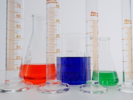
Acceptance for chemical service is not a paper claim — it is a test result. ASTM C581 (Standard Practice for Determining Chemical Resistance of Thermosetting Resins Used for Glass-Fiber-Reinforced Structures) and ISO 175 (Plastics — Methods of test for the determination of the effects of immersion in liquid chemicals) are the two governing methods. The workhorse protocol is 28-day immersion at the service temperature in the actual process fluid or a representative simulant, with flexural strength and Barcol hardness retention measured at 7, 14, 28 and sometimes 56 days. A widely cited acceptance line is 80% flexural-strength retention at 28 days; for more aggressive service, suppliers and end users push the spec to 56 days with 85% retention. [S3]
Test fluid selection is part of the spec, not an afterthought. Hydrochloric acid, sulfuric acid (varied concentrations), sodium hydroxide, sodium hypochlorite, and organic solvents (acetone, MEK, toluene) are the standard battery. The published SOFC-sealant data shows that even small shifts in glass composition — 0.5 mol% changes in BaO, SrO, or La2O3 — measurably alter the chemical-durability envelope, so composition alone is not a substitute for immersion testing [S1]. For high-temperature or high-purity service, the same logic carries across to optical glass and fused-silica feedstocks, where sub-micrometre additive manufacturing now reaches sintering temperatures near 1200 °C and demands tight control of impurity-driven attack [S2].
Gate 5 — Application Match: Tanks, Ducts, Piping, Scrubbers
Once the four upstream gates are closed, the application match is a final check. For atmospheric and above-ground tanks to ASTM D3299, the standard lay-up is a C-glass or Nexus veil inner surface (chemical barrier), a vinyl-ester inner corrosion liner at 2.5–6.0 mm thickness, structural E-CR or E-glass roving, and an outer paraffin or resin-rich coat. For underground petroleum storage to UL 1316 / UL 1746, the same architecture is wrapped in a hydrostatically tested outer shell. For ductwork handling acidic fumes, vinyl-ester with a Nexus veil typically runs thinner (3–5 mm total) and the structural mat count drops. [S1]
Scrubbers, which combine chemical and thermal load, often justify S-2 glass at the wetted zone for the temperature margin. Process piping to ASTM D2992 or D2996 uses continuous E-CR roving with no chopped mat in the chemical barrier — the published abrasion study confirms that adding chopped glass to a cementitious matrix changes the failure mode, the same logic that drives process engineers to keep a continuous-fiber architecture in the wetted zone [S3]. For non-process architectural uses, glass curtain wall and sight glass selections follow a different gate set — primarily optical and mechanical — and should not be conflated with chemical-tank glass selection.
Limits, Failure Modes and What the Spec Cannot Do
Glass fiber selection is bounded by three hard limits. First, hydrofluoric acid attacks all silicate glass — there is no glass grade that resists HF, and the spec must call for a non-silicate barrier (thermoplastic liner, carbon, or a polymer-only design) when HF is present. Second, hot caustic above roughly 50 °C and above 5% NaOH will degrade even E-CR glass; the standard workaround is a thermoplastic or vinyl-ester-rich liner with the structural glass isolated from the wetted surface. Third, sustained temperatures above the resin glass-transition temperature will relax the fiber–matrix stress transfer long before the fiber itself fails — for typical vinyl ester, the Tg sits near 100–110 °C, and the spec line should keep the wetted skin below this limit. [S2]
Two failure modes deserve to be called out by name. Osmotic blistering, visible as raised bumps on the inner surface, is the signature of wicking along the fiber under a concentration gradient; it is a sizing or veil problem, not a resin problem. Stress cracking at the inner surface, visible as a fine craze pattern, is the signature of resin under-cure, thermal cycling, or wrong resin selection; it is not a fiber problem. Specifying higher glass grade will not fix either of these, and pretending it does is how budgets get spent without changing the outcome.
Standards, Sources and Tracking Signals
Core standards governing this gate set: ASTM D578 (glass fiber strand), ASTM C581 (chemical resistance of thermosetting resins used in glass-fiber-reinforced structures), ISO 175 (immersion in liquid chemicals), ASTM D3299 (filament-wound tanks), ASTM D4097 (contact-moulded tanks), ASTM D2992 / D2996 (FRP pipe), UL 1316 / UL 1746 (underground petroleum tanks). The chemical-resistance test sequence — flexural-strength and Barcol-hardness retention at 7, 14, 28 and 56 days on immersed coupons — should appear in the procurement document by name, not just by outcome. [S3]
Composition and phase-fraction data published in peer-reviewed glass-ceramic sealant work remains the cleanest open reference for the oxide envelope that defines E, E-CR, and S-2 grades; the SiO2 47–49 mol%, Al2O3 1.2–1.7 mol%, B2O3 1.7–2.0 mol% window is the target range for chemical-service glass fiber production [S1]. Next signal worth tracking: supplier disclosure of silane type and film-former fraction on individual roving data sheets — when the spec line moves from “sizing compatible with vinyl ester” to naming the silane and the LOI band, the in-service failure rate on chemical tanks typically drops. Related engineering material choices follow a similar gate-set logic; for the seal-and-elastomer side of the same equipment, the PTFE vs industrial rubber selection frame covers the static and dynamic seat cut that sits next to a chemical tank, and the casting-ladle vs degassing-unit selection frame is a useful reference for the upstream melt-handling side where the glass reinforcement eventually ends up.