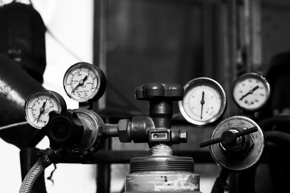
Globe valves are accepted on vertical or horizontal pipe, but the stem must never point downward and flow must enter under the disc following the cast arrow on the body, per current OEM installation guidance [S1][S4]. Eflow Valve specifies pipe supports under the valve for sizes above DN 100 mm, because the valve body cannot carry pipeline weight, and misaligned flanges will crack a cast iron body during bolt-up [S1].
The install sequence mirrors any flanged isolation valve: align flanges, seat the gasket, hand-tighten bolts, then torque in a star pattern. Gate valve installation practice on water lines uses the same four mechanical steps, which is why EPC crews often standardize the procedure across valve types [S6]. For full type-level context before you install, the globe valve types and classifications spec map breaks down Z, Y, angle, and bellows patterns against pressure, temperature, and throttling duty.
Allowed Stem Positions and Why Stem-Down Is Forbidden
Eflow's installation matrix lists manual handwheel globe valves as acceptable in stem-up or stem-sideways positions only, with stem-down explicitly excluded because packing cannot retain seal when the stem is loaded in tension by gravity and process pressure [S1]. Kosen's Y-type installation guide adds that the inclined stem and seat sit at roughly 45 degrees to the pipe axis, so the same up-or-sideways rule applies, with the medium entering below the disc to assist sealing [S2].
Electric and pneumatic actuators change the rule: the drive must sit stem-up because the motor mass bends a horizontal stem, wears the packing, and pulls the stem packing gland into a leak path; outdoor actuators also need a shelter because rain and UV degrade electric components quickly [S1]. Fleyenda's 2026 type guide repeats the same stem-up constraint as a hard installation consideration, not a preference, for any motorized configuration [S7].
Flow Direction: Under the Disc, Follow the Arrow
Globe valves are unidirectional, and Kosen's 2026 Y-pattern guide states that flow must enter beneath the disc and exit through the inclined outlet, so system pressure assists the disc against the seat and unloads the stem packing [S2]. Hearken's 2026 primer echoes the same rule, calling "flow under the seat" the standard convention for most globe valve designs [S4]. Fleyenda flags directional installation as a primary consideration when commissioning any new globe valve [S7].
DVS's three-step inspection guide (Jun 2026) documents the failure mode when this rule is violated: media acting on top of the disc lifts it off the seat during closure, which accelerates seat wear, raises operating torque, and can produce internal leakage even with the handwheel fully torqued [S5]. For steam and high-temperature service, the same reversed-flow condition also causes disc vibration and audible flow-induced noise, both early indicators of seat damage [S5].
Gasket, Flange, and Pipe-Stress Specs for Vertical Runs
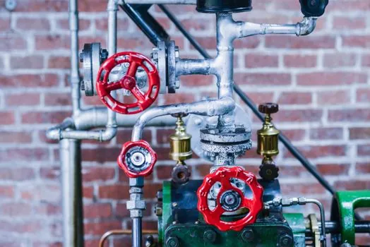
Eflow publishes a working gasket table for vertical globe valve installations: EPDM rubber to 16 bar and 0 to 60 degrees C for cold water, PTFE to 70 bar and -120 to +150 degrees C for chemical service, and paronite to 63 bar and -50 to +450 degrees C for high-heat steam lines [S1]. These pressure and temperature envelopes are practical starting points, but the final gasket call should be cross-checked against the flange class (ANSI 150, 300, 600) and the project piping class, not picked from the table alone.
Flange alignment is the single most common cause of body cracks on vertical installs, because installers compensate for pipe misalignment with thicker gaskets, which creates a soft spot and bends the flange face under torque [S1]. The Eflow procedure explicitly bans using gasket thickness to fix a bad pipe angle, and instead requires pipe supports under the valve plus axial compensators on long straight runs to absorb thermal growth [S1]. For very long vertical steam lines, this support layout is what keeps the bonnet-to-body joint from re-tightening or loosening under thermal cycling.
Comparison: Z-Pattern vs Y-Pattern vs Angle-Pattern Install
NTGD's May 2026 selection guide organizes the three body patterns against the four criteria that drive installation: flow path, pressure drop, throttling behavior, and typical service [S3]. Z-pattern (T-pattern) is the default for general throttling where higher pressure drop is acceptable, Y-pattern lowers pressure drop by angling the stem and seat at about 45 degrees for smoother flow, and angle-pattern replaces a 90-degree elbow while reducing joint count [S3][S4].
For install engineers, the comparison reduces to three rules: Z-pattern is the easiest to mount because the body is symmetric and the flow arrow points straight along the line; Y-pattern needs more clearance around the inclined stem, so handwheel or actuator swing radius must be checked against adjacent piping and insulation; angle-pattern saves one welded elbow but locks the installer into a fixed 90-degree turn, so line routing and pipe support locations must be confirmed before the valve lands [S3][S4][S7].
Wrong-Direction Field Symptoms and Acceptance Criteria
DVS's three-step inspection (Jun 2026) defines a clear symptom-to-cause map for reversed flow: difficulty opening, higher stem loading, packing box leakage, and in steam service disc vibration and abnormal noise all point to media pressure acting opposite the design intent [S5]. The acceptance test is mechanical: the handwheel must open smoothly to full stroke without binding, the packing must stay dry at operating pressure and temperature, and the closed valve must hold bubble-tight seat leakage per the project-specified seat class (Class IV, V, or VI).
DVS also publishes a decision rule on whether to repair immediately or defer: low-pressure systems with no leakage or torque anomaly can wait for the next planned outage, but persistent internal leakage, inability to achieve full shutoff, excessive vibration, or packing leakage all require prompt correction, and any high-pressure steam, flammable, toxic, or explosive service must be fixed under safety procedure, never by disassembling under line pressure [S5]. Temporary mitigation, such as retorquing the packing nut, is acceptable only to stop a leak short term, not to substitute for reorienting the valve.
Pre-Commissioning Checklist Before Hydrotest
Three documents must agree before torque is applied: the piping isometric, the valve body arrow, and the P&ID flow direction, and any disagreement is grounds to stop and re-verify per DVS's commissioning advice [S5]. Bolted-bonnet versus pressure-seal bonnet choice also matters at this stage, because Hearken specifies pressure-seal bonnets for high-pressure power-plant service where internal pressure actually tightens the seal as it rises [S4]. For a balanced view on adjacent isolation hardware, the gate valve advantages and disadvantages engineering guide is a useful counter-reference, since gate valves are bidirectional and tolerate much higher solids loading than globe valves in the same line.
Track two signals on the next project review: any rising hydrotest failure rate on flanged globe valves at DN 100 mm and above, which would point to a pipe-support or flange-alignment gap; and any field report of reversed-flow symptoms on a Y-pattern install, which would point to a P&ID-versus-body-arrow mismatch. Either signal is a leading indicator of install-procedure drift before it shows up as a seat-leakage failure in service.
The underlying component specifications are covered under globe valve, linear guide, and crossed roller guide.