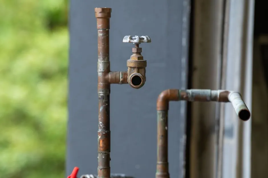
Most field failures of wedge gate valves on water, steam and process lines trace back to installation error rather than metallurgical defect: flange misalignment, welding heat on a seated elastomer, an inverted stem orientation, or a body arrow that disagrees with the P&ID [S1][S2].
The scope below covers standard flanged industrial gate valves in sizes 2" through 24" for isolation service; it does not replace the manufacturer IOM, the project piping class, or applicable ASME B16.34 / API 600 documentation that governs a specific pressure class and material combination [S2][S5].
Pre-Installation Inspection: Four Concrete Checks Before the Valve Lifts Off the Skid
Confirm nameplate data first: size, pressure class, body and trim material, end connection (RF/RTJ flange per ASME B16.5, BW per ASME B16.25, or flanged), and seat configuration must match the line spec [S2]. A 150-class gate valve installed on a 300-class line will pass a hydrotest at low pressure and then leak under operating load.
Inspect the body, stem, wedge and seat faces for transit damage: bent stem, scratched seat, loose bonnet bolting, or a handwheel that does not turn freely through the full stroke [S1]. On a 12" API 600 wedge gate, a full open-close cycle takes on the order of 60 handwheel turns because the wedge must lift roughly one bore diameter [S5]; if 60 turns does not produce full travel, the stem nut is misassembled or the stem is bent.
Clean the line before lifting the valve in: weld slag, mill scale, rocks and construction debris lodged between wedge and seat are the single most common cause of a "valve will not close" callout at commissioning [S1][S2]. On slurry or raw-water service, specify a knife gate valve instead of a standard wedge gate, because the sliding blade cuts through packed solids rather than jamming against them [S3][S5].
Mechanical Installation Procedure: Flange Alignment, Gasket and Bolt Sequence
Align the pipe flanges first, then lift the valve in: never use the valve body to correct pipeline misalignment, because induced body stress warps the seat pocket and produces a chronic line-contact leak that no amount of repacking will fix [S1][S2]. Adjust the pipe supports or re-cut the pipe until the gap between flanges is parallel and concentric within the gasket manufacturer's tolerance.
Seat the gasket on a clean, undamaged flange face; a scratched RF face or a mis-centred gasket is the second most common source of an external flange leak [S1]. For RTJ service, verify the ring groove is clean and the ring number matches the flange class.
Tighten flange bolts in a diagonal cross pattern in at least three controlled passes (30%, 60%, 100% of target torque) so the gasket load is even; a one-sided torque sequence locally crushes the gasket and lifts the opposite side, producing the classic "leaks at 9 o'clock, dry at 3 o'clock" pattern [S1].
Weld after the valve is out of the line, not before: weld spatter and HAZ heat above roughly 200°C will damage soft seats (EPDM, NBR, PTFE) and can distort a metal seat that has already been lapped [S1]. On hot systems, bring the line up to operating temperature with the valve in the half-open position to equalise body temperature before the first full close [S2].
Orientation: Stem-Up Preferred, Stem-Down Avoided, Inverted Reseated Before Use
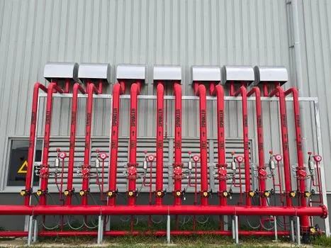
The default rule on a flanged industrial gate valve is stem vertical and handwheel up; this keeps packing immersed in any condensate, prevents sediment from packing into the stuffing box, and gives the operator clear visual indication of open versus closed via the rising stem [S1][S2].
Horizontal-pipe runs are acceptable when the stem remains vertical by using a yoke-mounted or leg-supported valve, but a stem-down or fully inverted installation is generally avoided on critical service because packing cannot be serviced without draining the line and any solids in the flow drop directly into the seat area [S2].
For OS&Y (outside screw and yoke) designs, allow full stem-travel clearance above the handwheel equal to one bore diameter plus the thread engagement length; an OS&Y installed in a low-clearance trench will not be able to open fully and is commonly found "stuck at 80%" because the yoke hits the ceiling slab [S2][S5].
Flow Direction vs Installation Orientation vs Open Direction
These three indicators are not the same thing and must be checked separately: flow direction is the normal process flow shown on the P&ID; installation orientation is the physical stem/handwheel position relative to the pipe; open direction is which way the handwheel turns to open the valve (most clockwise-close, but rising-stem gear-operated units are often the opposite) [S2].
On a standard wedge gate, flow direction is usually bidirectional and the body arrow, if cast, indicates the recommended rather than mandatory direction; on a unidirectional knife gate valve, the arrow, the "SEAT" marking and the pressure-side-when-closed logic must all agree, or shutoff performance drops sharply because the gate is being pushed off the seat by line pressure instead of into it [S3].
For a centrifugal pump discharge isolation, always install the block valve on the pump side and the check valve on the tank side; reverse this and the pump sees the full check-valve slam on every stop, which the gate valve is then expected to contain on the next start [S2].
Common Installation Mistakes and the Failure Mode Each One Produces
Forcing a misaligned flange pair produces a body strain that walks the seat pocket out of round: symptom is a valve that passes hydrotest but weeps at the gate-seat interface at operating pressure within days of start-up [S1][S2].
Welding adjacent flanges with the valve in place scorches the seat and packing: symptom is a valve that opens and closes smoothly on the bench but seizes or leaks externally on the first hot cycle [S1].
Installing a unidirectional knife gate backwards so pressure pushes the gate off the seat: symptom is a valve that holds bubble-tight from one direction and passes 10-30% of line flow from the other, which is misinterpreted as a worn seat [S3].
Skipping the post-installation open-close check before pressurising: symptom is discovering at first system fill that the handwheel is jammed, the stem is bent, or a factory-installed transit block was left in place, at which point draining and re-lifting are required [S1][S2].
Throttling with a gate valve (holding it at 20-40% open): the partially exposed seat edges are eroded by continuous high-velocity flow, producing a valve that will not shut off when finally required; the cure is to specify a ball valve or globe valve for any control duty, and reserve gate valves for full-open / full-close isolation only [S5].
Commissioning, Documentation and What to Record for the Maintenance File
Before line-up, stroke the valve through at least three full open-close cycles against an unpressurised line and confirm the position indicator matches the actual gate position; record handwheel turns from full close to full open as a baseline for future torque trending [S2].
Perform the system hydrotest with the gate valve in the half-open position so test pressure acts on the body and seat cavity simultaneously, then close and re-open against full test pressure as a seat-leakage check; API 598 and ISO 5208 are the typical acceptance references for allowable seat-leakage rates by class [S2].
Record and file with the maintenance system: as-installed orientation, handwheel turn count, body arrow versus P&ID flow arrow agreement, gasket type and lot, bolt torque values, hydrotest pressure and observed leakage rate, and the date of first successful open-close under system pressure [S2]. These five data points are the minimum needed for the next planned outage to diagnose seat wear or packing replacement, and they convert a generic ball valve TCO exercise into a defensible spares-and-replacement forecast, as detailed in the parallel ball-valve total-cost analysis.
One trackable signal for follow-up: the divergence between manufacturer-stated unidirectional knife-gate body arrows and on-site P&ID flow direction is the single most common field re-work item on 2026 slurry and pulp-and-paper projects, and is worth a pre-lift verification walk on every unit. A second signal: any gate valve installed in a steam or hot-oil header should be flagged for a hot thermal-binding check at first cooldown, since a cold-closed gate in a hot body is the textbook setup for a seized wedge.