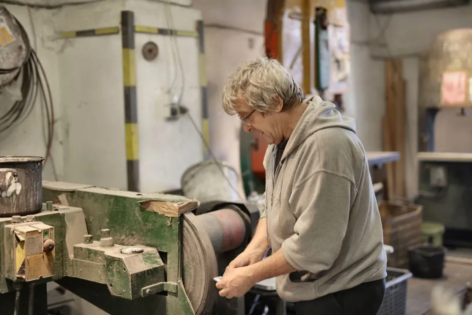
For hardware manufacturing runs of 30 g to 80 kg non-ferrous components, a gravity die casting machine is selected by matching the machine's mold envelope, clamping tonnage, tilting envelope, oil pressure, and cycle rate against the part's weight, wall thickness, draft geometry, and required annual volume before any tooling spend is committed [S1][S2][S5].
Hardware buyers should treat the machine spec sheet as a hard gate, not a wish list. Castings in this weight band typically hold linear tolerance of CT8 with wall thicknesses rated CT9 per ISO 8062, surface roughness around Ra 6.3 μm, and minimum wall thickness of 3 mm; if a hardware design breaches any of those, the GDC cell must be re-specified or the part re-drawn before a purchase order is placed [S5].
Mold Envelope and Clamping Tonnage as the First Gate
Mold envelope is the first hard gate, because a brass GDC cell such as the JD-AB500 accepts a maximum mold outlined diameter of 500 mm, a maximum mold weight of 150 kg, and a maximum mold baseplate distance of 510 mm, with a maximum clamping stroke of 270 mm [S1]. Hardware bracketry, lock bodies, and decorative brass fittings almost always fit inside this 500 mm by 510 mm window, but larger hardware subassemblies quickly exceed it and force a move up to a bigger cell or to a different casting route [S1].
Clamping tonnage scales with mold footprint and projected area, not just part weight. Production GDC cells for hardware commonly sit in the 15 tonne clamp range (a typical small-frame GDC rated 15 tonnes of clamping force, 1200 kg machine mass, 1700 mm by 1100 mm by 1900 mm footprint) [S2]. Going below 15 tonnes is workable for thin-wall hardware below roughly 1 kg, while heavier cast hardware and brass valve bodies normally call for larger tonnage and larger mold envelopes than the small-frame envelope can deliver [S1][S2].
Power, Hydraulics, and Tilting Envelope
Power and hydraulic envelope are the second gate, and they decide whether a GDC cell can run the alloy and the cycle rate the hardware program needs. The JD-AB500 brass machine draws 5.25 kW from a 380 V, 50 Hz three-phase supply, holds a 220 L oil tank, and runs the mold-side hydraulics at 50-70 bar [S1]. A smaller-frame GDC cell rated 3 kW, 3 HP motor, 220 V or 380 V supply, and a 700 °C maximum operating temperature envelope delivers roughly 92% efficiency at variable speeds up to 25 cycles/min, with integrated air/water cooling [S2].
Tilting envelope is the third gate, and it is where many hardware buyers get caught. Production brass GDC cells typically allow 0-90° lateral casting tilt, 0-110° pre-casting tilt, and 0-90° mold immersion, giving the foundry a full envelope for controlled pour, pre-cast set-up, and dip-coating of the die face [S1]. A simpler GDC frame with 0-90° adjustable mold tilt and a noise floor below 75 dB is enough for most hardware runs, but the pre-cast and immersion ranges are what separate a true production brass GDC from a basic manual tilting table [S1][S2].
Selection Criteria: Hardware Profile vs. Machine Class
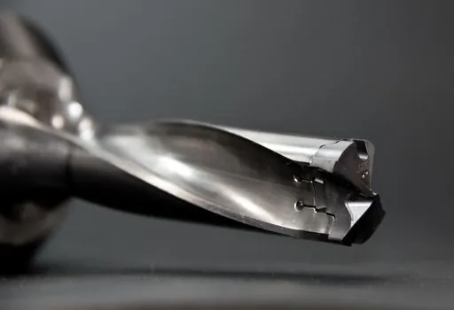
For hardware manufacturing, the practical selection tree is alloy, weight, tolerance, and volume, in that order. Brass and bronze hardware favors the JD-AB500 class of machine, with 50-70 bar hydraulics, 5.25 kW draw, and 0-110° pre-casting tilt, because the higher tilt range gives better control of brass flow and dross [S1]. Aluminum and zinc hardware favors a higher-cycle cell rated up to 25 cycles/min, 92% efficiency, and 700 °C melt-zone capability, paired with air/water cooling to keep the die face stable at thinner wall sections [S2].
Across the three main machine classes used in hardware, the comparison is structured, not qualitative. A small-frame GDC (around 1200 kg, 15 tonnes clamp, 3 kW, up to 25 cycles/min) suits hardware below roughly 1 kg and short-run brass fittings [S2]. A mid-frame brass GDC such as the JD-AB500 (500 mm mold diameter, 150 kg max mold, 5.25 kW, 50-70 bar, full 0-90°/0-110° tilt envelope) covers the bulk of medium hardware: lock bodies, valve trim, decorative brass, and small pump hardware up to 80 kg casting weight [S1][S5]. Larger hardware above 80 kg, or above 1000 mm maximum dimension, generally needs a heavier cell than the 500 mm mold envelope can accept and is more often routed to sand casting or low-pressure die casting instead of GDC [S5].
Use Cases, Tolerance Bands, and Process Limits
Gravity die casting earns its place in hardware manufacturing when the run volume justifies permanent tooling and the part can be drawn from a steel or cast iron mold. Compared with sand casting, GDC gives improved dimensional stability, better surface finish, and more repeatable production quality, and it is normally chosen once the project volume justifies the permanent mold [S6]. For prototyping, gravity-cast prototypes in sand, investment, or rubber plaster are used to approximate die-cast properties, but at the cost of longer solidification times and thicker walls than a production GDC will deliver [S7].
The hard process limits for hardware on a GDC cell are well documented: cast weight 30 g to 80 kg, maximum dimension 1000 mm, minimum wall thickness 3 mm distributed as evenly as possible, surface roughness around Ra 6.3 μm, and linear dimensional tolerance of CT8 with wall-thickness tolerance of CT9 per ISO 8062 [S5]. Draft angles have to be specified against wall and rib height rather than picked from a generic table, and any geometric tolerances that drive function must be marked on the drawing so the foundry does not guess at them [S5]. For non-ferrous hardware sourcing, GDC is also the route that pairs with permanent steel or cast iron tooling for repeatable production, which is why it dominates brass hardware, aluminum hardware, and lead-free zinc hardware at production volumes [S6].
Who GDC Is For, and Where It Is the Wrong Choice
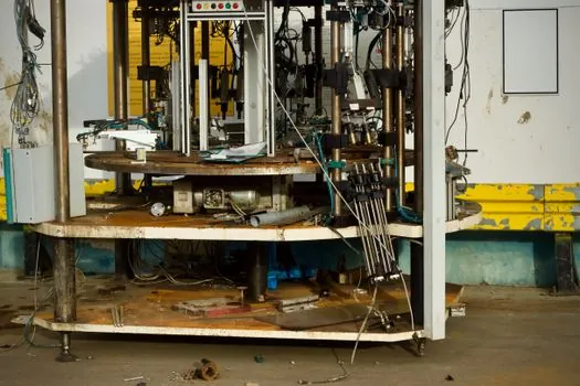
GDC is the right cell for hardware buyers who need 30 g to 80 kg non-ferrous castings at production volume, with CT8 linear tolerance, surface finish near Ra 6.3 μm, and a permanent steel or cast iron mold that will pay back across the program [S5][S6]. It is also the right cell where the buyer needs a tilt envelope of 0-90° on the casting axis, 0-110° on pre-cast, and integrated cooling to hold the die face steady on long runs [S1][S2].
GDC is the wrong cell when the hardware part is below 30 g or above 80 kg, when wall thickness drops below 3 mm, when the maximum dimension crosses 1000 mm, or when the run volume is too low to justify permanent tooling [S5]. It is also the wrong cell when the buyer actually needs a high-pressure die casting cell for thinner walls and tighter tolerances, since gravity-cast prototypes and GDC production both carry longer solidification times and thicker-wall requirements than high-pressure die casting delivers [S7]. For hardware programs that need to bridge GDC and HPDC decisions, the gravity die casting machine selection map for automotive parts covers the alloy-and-volume trade-offs, and the gravity die casting machine selection for aerospace components: 2026 spec map covers higher-tolerance hardware where CT8 may not be tight enough. Buyers weighing GDC against an aluminum die casting machine for thinner-wall hardware should match the tolerance and wall-thickness spec, not the cycle rate, because GDC's CT8 band is the binding limit, not its cycles per minute.
Spec Mapping, Sourcing, and What to Track Next
A practical hardware sourcing spec maps four numbers from the machine data sheet against four numbers on the part drawing: mold envelope (500 mm max diameter, 510 mm baseplate distance on a JD-AB500-class cell) against the part's bounding box and projected area; mold mass limit (150 kg) against the finished tool weight; oil pressure (50-70 bar) and clamp tonnage against the projected area and draft forces; and the tilt envelope (0-90° lateral, 0-110° pre-cast, 0-90° immersion) against the pour strategy the foundry plans to run [S1]. Add the foundry's quoted cycle rate (commonly up to 25 cycles/min on small-frame GDC), efficiency near 92%, and a noise floor below 75 dB to lock the cell to the plant layout [S2].
Trackable signals to watch over the next sourcing cycle are the oil-tank capacity (220 L on the JD-AB500 class) versus any move to a smaller tank on compact cells, the maximum operating temperature (700 °C) versus the alloy's pour temperature, and any tightening of ISO 8062 CT bands that the buyer is willing to pay for in a permanent mold versus the CT8 baseline [S1][S2][S5]. Buyers who can hold CT8 and 3 mm minimum wall on their hardware drawing will fit a wide envelope of GDC cells; buyers who cannot will need to re-draw the part before any machine is ordered.
Component reference pages worth checking: die casting machine.