
Guided wave radar (GWR) level meters, also marketed as TDR-guided wave radar level transmitters, send low-energy microwave pulses down a probe and time the return echo from the liquid surface [S1][S5]. They are specified for applications where free-space radar level meters struggle — turbulent boiling liquids, foam layers, low-DK hydrocarbons, and narrow stilling wells — because the probe physically guides the pulse to the surface and ignores most obstructions in the tank [S1][S3].
For engineers comparing continuous level technologies, GWR sits between non-contact radar level meter (more flexible, more affected by foam) and contact probes such as [magnetostrictive vs capacitance level transmitter: 2026 selection specs](/news/magnetostrictive-vs-capacitance-level-transmitter-2026-selection-specs.html) options; pricing is typically 1.5–3× an ultrasonic unit but lower than a free-space radar in the same DN100 process connection [S1][S2].
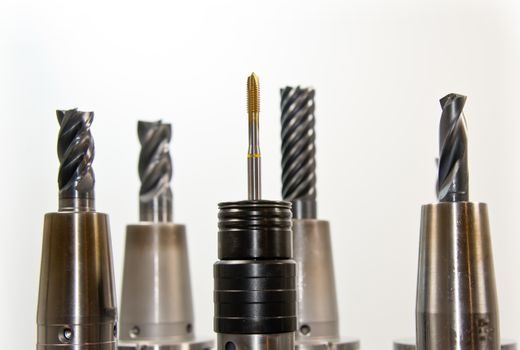
Probe Type vs. Medium: Coaxial, Rigid Rod, Flexible Cable
The probe architecture — coaxial, single rigid rod, or flexible cable — is the first selection gate and is dictated by the medium dielectric constant (Dk), viscosity, and the tank's available nozzle [S1][S2]. Coaxial probes concentrate the pulse in a defined tube and tolerate low-DK liquids down to Dk 1.4, but they foul with heavy sludge, coating liquids, or crystallising chemistries; rigid rod probes handle higher viscosities and are easier to clean in hygienic service; flexible cable probes extend the practical measurement range into 30 m+ silos and bulk-solid hoppers [S2][S3][S5].
ABB's LWT300 series is offered in two mechanical sizes — the LWT310 in a 19 mm (3/4 in) NPT process connection and the LWT320 in a 38 mm (1-1/2 in) NPT connection, both with flanged variants — which maps directly to the trade-off between small nozzle compatibility and heavier rod/cable construction in larger tanks [S3]. A first-pass rule used by panel builders: pick a coaxial probe for clean low-DK liquids in stilling wells, a rigid rod for hygienic or coating liquids, and a flexible cable only when the measurement range exceeds what a rigid rod can reach without touching the tank bottom [S2][S3].
Process Pressure, Temperature, and Material Limits
Current GWR process envelopes from leading OEMs cluster around −1 to 17 bar and −40 °C to +150 °C on stainless-steel wetted parts, which covers the bulk of atmospheric storage, light-pressure chemical reactors, and hot CIP service [S1]. The OMEGA LVRD10 TDR-guided wave radar is published at −1 bar to 17 bar (246.56 psi) and −40 °C to +150 °C (302 °F) with an IP66 stainless-steel housing and 4-20 mA / 3-wire output [S1].
Where the envelope is exceeded, the selection problem changes: above 150 °C the GWR probe needs a high-temperature extension neck or a remote electronics head, and above 17 bar the operator should verify the probe's mechanical pressure rating against the guided wave radar level meter flange class and gasket choice, not just the electronics rating [S1][S2]. For cryogenic or sub-zero brine duty, check the O-ring compound as carefully as the probe rating, because elastomer limits — not the microwave electronics — typically fail first [S1].
Output Protocols and Integration

4-20 mA with HART remains the dominant wiring scheme for new GWR transmitters, but RS-485 Modbus and FOUNDATION Fieldbus variants are widely listed for direct DCS or PLC integration [S1][S2]. The OMEGA LVRD10 ships as a 4-20 mA / 3-wire device, while the Riels RLFP explicitly carries 4-20 mA, HART, RS-485 and Modbus on the same product page, with selectable fail-safe signal output diagnostics [S1][S2].
This matters when retrofitting older automatic level controllers that still expect a pure 4-20 mA loop: a HART-over-4-20 mA device will read as a 4-20 mA signal to a legacy input card, while a true RS-485 or fieldbus device requires a different card or a gateway — so the procurement spec must lock the output variant before quoting, not after [S1][S2]. For SIL loops, select the Fail-Safe Diagnostics with Selectable Signal Fail-Safe Output feature set (as published on the LVRD10) and verify that the safety manual matches the exact firmware revision [S1].
Interface Measurement and Emulsion Layers
GWR is also specified for level-and-interface duty on separators, where the same probe tracks the top liquid surface and a second, lower echo from an underlying immiscible phase — typically oil over water, or aqueous over hydrocarbon [S3]. The ABB LWT300 and the legacy Rosemount 3300 series are both published as guided wave radar level and interface transmitters, with the LWT300 using its LevelExpert™ algorithm to discriminate the real interface from spurious echoes off agitator blades, heating coils, and tank welds [S3].
For interface service the upper-phase Dk must be at least ~10× the lower-phase Dk; if the difference is smaller the lower interface echo collapses into noise and the meter will only report total level [S3]. Compared with a capacitance probe, the [magnetostrictive vs capacitance level transmitter: 2026 selection specs](/news/magnetostrictive-vs-capacitance-level-transmitter-2026-selection-specs.html) show GWR is more tolerant of coating build-up but less responsive on foaming interfaces, and it carries a higher unit price.
Comparison of Main Probe Options on 4 Decision Criteria
Coaxial, rigid-rod, and flexible-cable probes can be lined up on the four criteria that most often drive a panel-builder's choice: low-DK ability, hygienic/clean-in-place suitability, max measurement range, and tolerance of coating/build-up [S1][S2][S3].
Coaxial — best low-DK ability (Dk ≥ 1.4), best for stilling wells, worst tolerance of coating; Rigid rod — moderate low-DK ability, best for hygienic / clean-in-place service, moderate tolerance of coating; Flexible cable — adequate low-DK ability (with reference target tuning), suited to 30 m+ silos and bulk solids, tolerant of build-up but not recommended for agitated tanks with lateral forces on the cable weight [S1][S2][S3].
In side-by-side screening this is usually the fastest way to drop from three candidate probes to one, before the tank geometry and nozzle schedule are even drawn [S1][S2][S3]. Where ultrasonic is being considered instead, ultrasonic level meter options are cheaper but unsuitable for foam, vapour, or vacuum service — a separate evaluation track that often runs in parallel to the GWR spec.
Where GWR Fails: Foam, Heavy Build-up, Low-DK Vapour
Despite a long list of strengths, GWR has real failure modes the spec must address up front [S1][S2][S3]. Heavy foam that completely absorbs microwave energy will suppress both the surface and the interface echo; thick sticky build-up on a coaxial probe will short-circuit the pulse and shift calibration; installation too close to the tank wall or to a metal ladder will introduce a strong false echo that even auto-learn algorithms can mistake for level on a slowly-falling ramp [S3].
In free-space radar units, an tdr level meter probe variant that uses a reference target at the probe end helps the firmware distinguish the real surface from fixed obstacles, but the plant must still allow a clear zone — typically 150–300 mm — between the probe and any internal fitting for the algorithm to work reliably [S3]. For genuinely hostile services (molten salts, strong caustics above 150 °C, slurries with metallic particles) most specifiers escalate to a different technology rather than chase a GWR rating with custom alloys and exotic seals.
Standards, Diagnostics, and Procurement Cues
Procurement specs on GWR typically reference IEC 60079-0/1/11 for explosion-proof enclosures, ATEX 2014/34/EU for European hazardous-area use, and NACE MR0175 for sour-service wetted parts — the standard revision dates should be locked to the call-out in the project datasheet, and any deviation recorded in the vendor's deviation list [S1]. The 146-page Rosemount 3300 series reference manual (document 00809-0100-4811, Rev CA, dated February 2006) is still used as the baseline reference for level-and-interface GWR terminology and is worth pulling up when reading newer OEM datasheets.
The Riels RLFP datasheet explicitly carries pharmaceutical, food, hygienic, and corrosive-environment applications alongside storage-tank and pressurized-vessel service, indicating that hygienic-style tri-clamp GWR probes are now a normal catalogue line rather than a custom build [S2]. A trackable procurement signal: lock the probe material, gasket compound, output protocol, and fail-safe mode on the purchase order; a comparable signal on the operations side is to verify that the asset's diagnostic event log (echo curve snapshot) is exported to the CMMS at commissioning, so the next planned shutdown can be justified against actual trending rather than guesswork [S1][S2][S3].
For a parallel flow-side selection that often comes up in the same revamp, [variable area flowmeter selection: 6 spec gates before you quote](/news/variable-area-flowmeter-selection-6-spec-gates-before-you-quote.html) is a useful cross-check on the same engineering checklist. Also, when custody-transfer interface measurement is the actual driver, escalate to a sound level meter-style ultrasonic or a free-space radar cross-check on a sample line; GWR on its own is rarely acceptable for fiscal metering in the standards panels familiar with this class of equipment.