Filter Q is dimensionless and defined as the ratio of a resonator's center frequency to its 3 dB bandwidth, so a bandpass filter centered at 1000 Hz with a 33.33 Hz 3 dB bandwidth has Q = 30 [S3].
The Q factor expresses stored energy divided by energy dissipated per cycle, and applies to series-tuned circuits, parallel-tuned circuits, transmission lines, microwave cavities, acoustic resonators, and RC active filters alike [S3]. The general physics definition uses energy stored in the resonator over energy lost in one radian of oscillation, with the bandpass form being the practical everyday equivalent used by RF engineers [S2][S6].
The three flavors of Q: loaded, unloaded, and external
Loaded Q (Q_L) is the figure of merit read directly off a filter's measured response curve and is calculated as the center frequency divided by the 3 dB bandwidth, which makes it the Q a buyer actually sees on a datasheet plot [S1][S5]. Unloaded Q (Q_u) describes the intrinsic loss of the resonator itself, stripped of external loading, and external Q (Q_e) captures the coupling between the resonator and the outside 50 ohm world. The relationship 1/Q_L = 1/Q_u + 1/Q_e is the workhorse equation that tells a designer whether loss is being dominated by the resonator's own dissipation or by the matching network [S5].
For an inductor the component Q is reactance over equivalent series resistance, and the same form applies to a capacitor, so a higher-Q component is one that approaches the ideal lossless part [S3]. Practical Q values vary by orders of magnitude across system types: dampers sit near Q = 0.5, tuning forks land around Q = 1000, and the Q of atomic clocks, superconducting RF cavities in accelerators, and high-Q lasers can reach 10^11 and beyond [S2].
How Q controls bandwidth and selectivity
A higher Q narrows the passband and sharpens selectivity, while a lower Q widens the passband at the cost of letting nearby frequencies through, and the half-power or 3 dB points f1 and f2 are the standard markers for measuring that bandwidth [S3][S4]. In a series-tuned circuit the voltage across the inductor and capacitor climbs to roughly Q times the applied voltage, and in a parallel-tuned circuit the circulating current reaches roughly Q times the input current, which is why high-Q tanks are both useful and dangerous [S3].
Channel-isolation work such as RF and IF filtering in radio receivers favors high Q because it filters out adjacent stations, whereas audio and broadband data applications deliberately choose lower Q to pass a wider range of frequencies without ringing [S2][S4]. On a Bode plot the geometric mean of the two 3 dB points equals the center frequency (f_c^2 = f1*f2), which gives a quick sanity check whenever a measured curve looks asymmetric [S3].
The insertion loss penalty built into every Q choice
Overall losses through a resonator increase as Q drops, and the loss increase with frequency is steeper for low-Q resonators, so the same filter topology can look acceptable at 100 MHz and fall apart at 1 GHz if Q is not held up [S5]. In RF engineering shorthand, saying "high Q" about insertion loss generally means low insertion loss, and saying "high Q" about selectivity generally means steep skirts, so the term carries two different promises on the same plot [S5].
Higher-Q passive filters demand tighter-tolerance inductors and capacitors with lower equivalent series resistance, and those components cost more and are harder to source, which is the real reason a Q = 200 filter costs several times more than a Q = 20 equivalent in the same package [S4]. The harmonic filter category in particular shows this trade-off: passive shunt harmonic filters on industrial busbars are sized by the same Q-vs-bandwidth reasoning, and the Q value you select directly sets how narrow a notch you can carve around the 5th, 7th, or 11th harmonic.
Component Q, pole Q, and bandpass Q: pick the right one for the question
Three definitions of Q are in regular use and they answer three different questions. Component Q addresses a single inductor or capacitor and is X_L/R_s or X_C/R_s, telling you how close that part is to ideal. Bandpass Q is the same as Q_L and is read from the 3 dB bandwidth of the assembled filter, with the caveat that the narrowband assumption breaks down once f1 and f2 are more than about two octaves apart, at which point the filter is usually a wideband structure built from cascaded sections rather than a single resonator [S5]. Pole Q is the most abstract of the three, derived from pole-zero plots, and it characterizes how a particular pole pair shapes the response across a defined portion of the curve.
Engineers specifying filters for power electronics, drives, and UPS systems should anchor decisions on bandpass Q (Q_L) because it is what the test sheet actually measures, while RF component buyers on a bill of materials should track component Q on the individual inductors and capacitors because that is what derates as frequency climbs. For more on how a tuned shunt branch fits into a broader mitigation plan, see the harmonic reducer reference and the construction-side construction machinery and equipment page where active harmonic compensators are being installed on hoist and crusher feeds.
Where the tradeoff shows up: RF, audio, power, and instrumentation
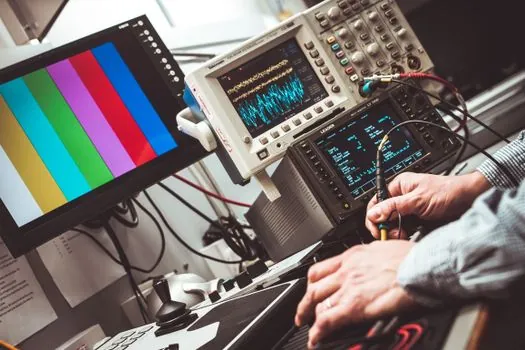
Telecommunications, radar, and instrumentation all rely on high Q to pull a weak signal out of a crowded spectrum, and the cost is the tighter tuning tolerance and the more aggressive component screening [S4]. Audio and broadband applications flip the priority, picking low Q so the response stays smooth across the audible band without resonant colorations. For a single-channel harmonic-compensation cabinet versus a four-channel rack, the cost split is driven less by Q and more by the number of parallel filter branches, a question covered in the one-channel vs four-channel controller and probe cost comparison. On the rotating-machine side, a single-axis vs triaxial accelerometer cost breakdown is a useful parallel because the same Q-bandwidth reasoning decides how many axes you instrument and at what bandwidth.
In the power-quality world, an L-C trap filter on a 480 V bus targeting the 5th harmonic at 300 Hz typically lands in the Q = 30 to Q = 60 range, and pushing Q above 100 narrows the notch so much that grid frequency drift and component aging drag the trap off target within a few seasons. Choosing a lower Q of 15 to 25 broadens the notch and keeps the filter effective across a wider frequency window, at the price of slightly higher circulating current and higher I^2R loss in the reactor, which is why filter vendors publish loss-versus-Q curves rather than a single Q number.
Limitations, failure modes, and verification points
The narrowband Q_L formula breaks when f1 and f2 are more than two octaves apart, and at that point the filter should be treated as a wideband cascade of sections rather than a single resonator [S5]. Loaded Q also drifts with temperature because the L and C values that set the resonant frequency both have temperature coefficients, and the resulting detuning flattens the response and erodes selectivity in the field long before any component fails outright. For passive harmonic filters on industrial networks, the practical mitigation is to specify detuning factors and to verify the Q on a network analyzer sweep before energizing, because the lab value of Q_u is rarely the value the bus sees after the reactor warms up under load.
Watch the 3 dB points on a vector network analyzer trace, confirm that f_c matches the geometric mean of f1 and f2, and compare the measured Q_L against the datasheet Q_u derated by the external coupling Q_e; if those three numbers do not line up to within roughly 10 percent, the resonator is either being loaded too heavily or the component Q has dropped below spec. The same Q-versus-loss reasoning shows up in the lamps and light fittings supply chain, where LED driver EMI filters are graded on insertion loss at the switching frequency and on Q at the harmonic notch, and on the air-quality side in air quality monitor front-end filtering where narrowband 50/60 Hz rejection sits inside the same Q-versus-bandwidth envelope. For a deeper look at the harmonics those filters are actually chasing, the power quality analyzer reference covers the measurement chain that closes the loop on a Q selection.
Track these signals over the next quarter: published Q-versus-insertion-loss curves on passive harmonic filter datasheets from major European and Chinese drive vendors, revised IEEE 519 and IEC 61000-3-12 guidance documents that mention Q explicitly in their mitigation examples, and the appearance of active harmonic compensators with programmable effective Q, which let operators retune the notch from a touchscreen rather than re-tap a reactor.