A detuned passive harmonic filter is built by connecting a line reactor in series with each capacitor step, with the L and C sized to resonate below the lowest dominant harmonic order, typically below the 5th (250 Hz on 50 Hz mains) [S3][S5].
The construction is widely applied at both low voltage (400-480 V) and medium voltage (2.4-34.5 kV) switchgear levels, with the reactor carrying full capacitor current plus harmonic current, and the capacitor rated for filtered operation at elevated voltage and current [S1][S2].
Why a series reactor sits in front of a capacitor bank
A bare capacitor forms a parallel LC resonant circuit with the network inductance, and if that resonance lands near a harmonic order present in the system, harmonic current is amplified, sometimes by an order of magnitude, before the harmonic reducer is even engaged [S3]. A series reactor raises the resonant frequency to a point where nothing lives (typically 189 Hz for 7% p=5th detuning on 50 Hz, 134 Hz for 14% p=3rd detuning), so the parallel resonance can no longer coincide with a real harmonic [S3][S5].
At harmonic frequencies above the tuning point, the LC pair presents inductive impedance, so harmonic current is blocked from entering the capacitor instead of being amplified into it [S3][S6]. The same reactor limits energising inrush (dI/dt limited by L) and contributes to short-circuit current limitation in the same physical hardware [S2].
Tuning and detuning factor: how the L and C values are picked
The reactor reactance is chosen as a percentage p of the capacitor reactance at mains frequency, called the detuning factor. Common values are p = 7% (tuned below the 5th harmonic, 4.2-4.9% absolute depending on grid impedance assumptions) and p = 14% (tuned below the 3rd harmonic) [S3][S5]. The tuning order h is then h = 1/sqrt(p), so p = 7% gives h ≈ 3.77, deliberately below h = 5 [S5].
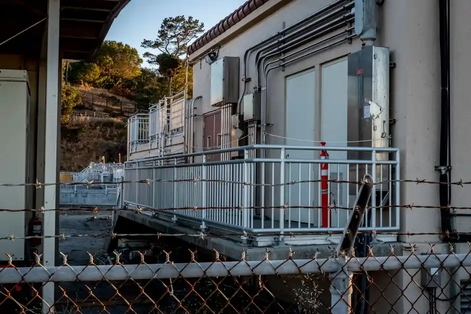
Controllix Midwest foundry casework used filter branches explicitly tuned to the 5th and 11th harmonics, with metal-enclosed construction rated for outdoor substation duty [S1]. Two-stage (broadband) designs add a damping resistor, while a single-stage LC is the most common topology for low-voltage power factor correction equipment [S5][S6].
Selection criteria: which detuning factor for which network
Use the network's harmonic profile to choose p. Lightly distorted LV networks (THDv < 5%, dominated by 5th from 6-pulse drives) take p = 7% as the economical default [S3][S6]. Networks with significant 3rd harmonic content (offices, single-phase SMPS, LED lighting, three-phase four-wire systems with neutral triplen currents) should select p = 14% or move to active harmonic filtering [S3].
Capacitor and reactor ratings must be reworked together, not independently. A p = 7% reactor drops the capacitor's effective reactive power by roughly 7% and raises its terminal voltage by the divider ratio; the bank must be re-specified for both the higher voltage and the harmonic current heating [S2][S5]. A rule of thumb engineers apply: capacitor failure rate rises roughly 15% for every 5 °C above rated ambient, so the thermal derating from harmonic current is a real cost, not paperwork [S3].
Filter topology comparison: passive detuned vs active vs broadband
Passive detuned (LC): simplest, lowest cost, fixed tuning, robust for predictable harmonic spectra; cannot adapt if the spectrum shifts toward higher orders or if 3rd content grows [S4][S6]. Active harmonic filter (AHF): power-electronic inverter injects cancelling current, adapts in real time, handles a wide range of orders including both odd and even, but at higher capex and a smaller footprint advantage [S2][S4].
Broadband / two-stage passive (LCL or LCR): wider absorption band, used when several harmonic orders must be sunk in a single branch, common in MV substation duty [S1][S5]. A short verbatim specification from the Controllix foundry case: "multiple metal-enclosed harmonic filter equipment, tailored with 5th and 11th harmonic tuning frequencies," illustrating that a single installation can carry two separately tuned branches on the same bus [S1].
Where the construction is used, and where it should not be
It fits: industrial plants with VFDs, six-pulse rectifiers, large UPS, arc furnaces, and rolling mills, where the harmonic spectrum is dominated by 5th, 7th, 11th, 13th and the bank is the lowest-impedance sink [S3][S4]. It fits MV utility capacitor banks, where detuning is mandatory before energising in harmonic-rich substations [S1]. It does not fit: networks with dominant 3rd harmonic and triplen neutral loading, unless p = 14% or higher is chosen, and it is not a substitute for IEEE 519 compliance at the point of common coupling on its own, the bank has to be measured there [S3].
For sensitive electronic loads, the filter is also not a voltage conditioner; pairing a detuned bank with an AHF is a common upgrade path when 5th/7th filtering is handled passively and residual orders are tracked actively [S2][S6].
Standards, limits, and measurable signals to track
IEEE 519 is the limit typically invoked at the point of common coupling to cap THD and individual harmonic distortion for both voltage and current; passive detuned banks are sized so the residual THD after filtering lands inside the IEEE 519 table for the relevant short-circuit ratio [S3][S4]. Capacitor standards governing voltage, kVAR, and dielectric endurance (the IEC 60831 family for LV self-healing capacitors, ANSI/IEEE 18 for shunt power capacitors) are the documents that define the re-rated voltage and current numbers a detuned bank must carry, not the bare 50/60 Hz ratings [S1].
One peer comparison worth opening before specifying: harmonic filter design topology trade-offs for the bus structure that sits behind the filter, and the passive vs active filter cost stack for capex framing in a 2026 plant upgrade.
For component-level specifications, see construction machinery and equipment, and harmonic filter.