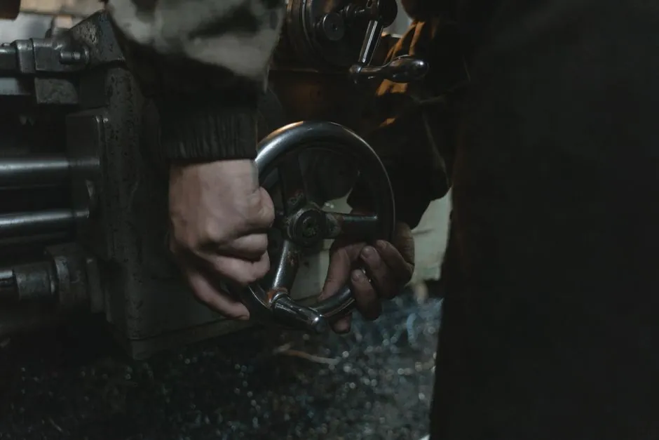
Steel mill auxiliary drives, including cooling beds, slab conveyors, furnace charging and billet handling, are typically specified around parallel-shaft (F series) and bevel-helical (MJ series) reducers with 0.18–220 kW ratings, 3.81:1 to 281.71:1 transmission ratios, and 94–96% mechanical efficiency per stage [S1][S6].
The selection logic has not changed: match the drive layout to the driven machine, lock the service factor to AGMA 6034 Class II or III, then verify ratio, thermal capacity, and overhung load before any brand decision [S2][S5].
Layout Family vs Steel Mill Drive Station
For a straight horizontal cooling-bed conveyor or a slab transfer line where the reducer sits on a flat bedplate parallel to the drive shaft, a parallel-shaft helical (F/FF/FAF series) gives the lowest cost per kilowatt, with the 87–157 frame sizes covering 0.75–90 kW and 4100–18000 N·m allowable torque at ratios from 4.12:1 up to 281.71:1 [S1].
For inclined or right-angle layouts (furnace charging, coil handling, run-out tables driven from the side), bevel-helical (MJ series) is the standard fit, with the right-angle bevel stage plus a helical stage typically landing in the 0.12–200 kW, 5–60 RPM output window used in steel plants [S2][S6]. For multi-megawatt main roll drives or heavy slab mills, the MTH/B-MTB class is what most engineering specs call out, again with right-angle bevel-helical geometry, but that is a custom-engineered, not a catalog, decision [S2][S5].
Service Factor and Duty Band: AGMA 6034 Bands
Under AGMA 6034, a 24-hour shock-loaded steel-mill conveyor is a Class III application with a minimum service factor of 2.0, not the 1.4 default most catalog pages print on the cover; a uniformly loaded screw conveyor at 3–10 h/day is Class II at 1.4 minimum, while a steady 8–10 h/day aux drive sits at Class I, 0.8 minimum [S2].
Design HP equals prime-mover HP multiplied by the applicable SF, so sizing at SF 1.4 instead of 2.0 on a slab conveyor cuts design HP in half and routinely shows up as gear-tooth fatigue at the first bearing-replacement interval, rather than at the calculated design life [S2]. For rolling-mill auxiliaries, a starting torque well above running torque is the rule, not the exception, which is the reason the SF 2.0 headroom is the floor, not the ceiling, on those trains [S2][S5].
Ratio, Stage Count and Per-Stage Efficiency
Per ISO 6336 / DIN 3990 cylindrical-gear geometry, a single-stage helical ratio caps near 7:1 before center-distance and tooth-profile constraints force a second stage; two-stage reaches roughly 50:1, and three-stage extends past 200:1 [S2]. A 20:1 or 29:1 ratio is therefore a two-stage unit, and any single-stage quote at 29:1 should be rejected on physics [S2].
Each helical stage takes 2–5% off mechanical efficiency, so a three-stage helical at 94% per stage delivers roughly 83% overall, and that loss has to be carried into the thermal calculation, not buried in the gearbox nameplate [S2]. On a per-mesh basis, a helical pair runs 98.5–99.5% under full load, well above worm gearing (50–90%) and on par with straight bevel gears, and that is the per-mesh figure that gets multiplied across the stage count [S4]. F-series published efficiency of 94–96% is the multi-stage gearbox figure, not a single-mesh number, and that distinction is what the cooling-bed heat exchanger is sized against [S1][S2].
Materials, Heat Treatment and Tooth Accuracy
F-series parallel-shaft gears use 20CrMnTi alloy steel with case-hardened tooth surfaces at HRC 58–62, core HRC 33–40, and shafts in 42CrMo at HRC 25–30, with housings in cast iron or ductile iron at HBS 190–240, and gear cutting to precision-grinding level 5–6 [S1]. For the larger frames that feed steel-mill mains, the alloy set widens to 18CrNiMo7 and 42CrMo4, finish-ground after case hardening to DIN 5–8 quality class, with double-helical (herringbone) gears running helix angles of 25–35° for maximum noise reduction and elimination of axial thrust [S4].
Lubrication is normally mineral gear oil in the ISO VG 220–460 band, with F-series housings rated for an oil-temperature rise of 50°C and a winding/housing rise of 40°C maximum, vibration under 20 µm, and backlash held to ≤20 arc-min on the standard grind [S1]. The contact-ratio and helix-angle choice is not academic: helical gears carry a total contact ratio of 1.5–2.5 against 1.2–1.6 for a spur gear at the same module, which is the mechanical reason the housing is 15–30% smaller than an equivalent spur unit at the same power, and why noise is 6–10 dB(A) lower at the same load and speed [S4].
Comparison: F (parallel) vs MJ (bevel-helical) vs MTH (heavy main drive)
The F-series parallel-shaft unit is the lowest-cost fit for a straight horizontal conveyor with the reducer on a flat bedplate, runs 0.18–90 kW (standard frames F37–F157), and lands ratios between 3.81:1 and 281.71:1; it is also the family that loses the most floor space when ratios go above 50:1 because it stacks three stages [S1][S2].
The MJ bevel-helical trades 3–5% efficiency at the bevel pair for a right-angle output and a smaller footprint, which is what furnace-charging, coil-handling and run-out-table drives usually demand, and the published range runs 0.12–200 kW, 5–60 RPM output, with the bevel stage cutting the overall ratio ceiling versus a two-helical unit [S2][S6]. The MTH / B-MTB class is reserved for multi-megawatt main roll and slab-mill drives where the catalog stops and the project specification begins; it is not a stock part and is the family most often paired with engineered cooling circuits, not the standard ISO VG 220 oil bath [S2][S5].
Helix Angle and Noise: Why Steel Mills Move to Herringbone
Single-helical gearbox geometry typically lands at 8–15° helix to keep standard thrust bearings in budget; pushing to 20–30° buys maximum noise reduction but forces a double-helical (herringbone) cut to cancel the axial thrust the steeper helix creates, and that is the configuration that shows up on the larger mill mains and marine main reduction gears [S4].
The mechanism is the progressive tooth engagement: a helical contact line begins at one end of the face and sweeps diagonally across the full width as the gear rotates, so the load onset is gradual rather than impulsive, and that is what cuts mesh noise by 6–10 dB(A) versus a spur gear of equal module, speed, and load, while also spreading the load across more teeth at any instant [S4]. For a steel-mill auxiliary, where the gearbox is mounted on a structure that transmits vibration into the operator floor, that 6–10 dB(A) gap is the difference between a working environment and a noise-compliance retrofit, and it is also why helical geometry has displaced spur gears in enclosed industrial units almost entirely [S4][S5].
Selection Gate: Inputs, Lookups, and What to Verify
A steel-mill helical reducer spec runs on four inputs and four lookups: motor RPM (1450 at 50 Hz, 1750 at 60 Hz), output RPM at the driven shaft, duty cycle in hours per day, and the shock-load character of the mill stand or conveyor; those feed the AGMA 6034 service-factor class, the ratio bracket with stage count, the gearbox family (F / MJ / MTH), and a thermal-plus-overhung-load check [S2][S5].
The F-series published ratings already embed a 94–96% efficiency at one or two stages, so the practical verification points are: (a) SF per AGMA 6034 (Class II at SF 1.4 minimum for 24 h/day steady, Class III at SF 2.0 minimum for 24 h/day with shock), (b) ratio feasibility per ISO 6336 / DIN 3990 (single-stage caps near 7:1, two-stage near 50:1, three-stage past 200:1), (c) oil-temperature rise inside the 50°C oil / 40°C housing limit, and (d) overhung load on the output shaft from the driven pulley, drum, or pinion [S1][S2]. For broader selection context on the wider helical gear reducer family, or for a baseline on gear reducer and gear coupling interfaces used on the same mill drive line, the cross-references carry the rating logic the steel-mill spec needs to keep aligned.
The next trackable signal is the published AGMA 6006 / ISO 6336 fatigue-life recalculation that the F37–F157 series is rated against: any mill that runs Class III duty with shock should ask the vendor for the calculated L10h hours at the actual application factor, not the catalog maximum, and confirm the case-hardened 20CrMnTi / 18CrNiMo7 surface at HRC 58–62 is the finish, not an option, on the order.
Component reference pages worth checking: gear reducer.