The helical gear reducer is the workhorse parallel-shaft unit in heavy industry: RENOLD's SMX line covers torque ratings above 10 kNm with 287 kW input power and 5:1 to 25:1 reduction ratios in a shaft-mounted package [S1].
Reference units now span 0.36 kW to 287 kW input power and 10 rpm to 750 rpm output speed, with single-reduction 5:1 and double-reduction 13:1 / 20:1 / 25:1 metric ratios (15:1 North American) as the standard offering [S1][S2]. A 2500 HP, 48:1 cement-mill drive weighing 80,000 kg shows how far the format scales for mineral-processing main gearboxes [S2].
Defining Geometry and Where Helical Units Fit
Helical gears cut with teeth at a helix angle (commonly 15°–25°) on parallel or crossed shafts, giving line contact instead of the point contact of spur gears [S1]. The format is the standard choice for parallel-shaft layouts above 5 kNm, and is the baseline against which cycloidal reducers, harmonic drives, and worm units are typically compared on efficiency and torque density. RENOLD publishes its SMX as a parallel-shaft helical unit with torque ratings above 10 kNm and shaft-mounted installation [S1]. Galbiati Group's cement-mill drive, 2500 HP at 750 rpm with a 48:1 ratio and 80,000 kg total mass, is a parallel-shaft helical build for mineral-processing main gearboxes [S2].
Hard Advantages: Efficiency, Load Capacity, Smoothness
Hardened and profile-ground helical gears are quoted as delivering maximum power transmission, smooth operation, and long life at maximum efficiency in OEM datasheets [S1]. The tooth-angle geometry produces multiple teeth in mesh simultaneously, which lowers vibration and noise versus spur equivalents at the same pitch. For example, a close-grain cast iron gear case on the SMX is rated for quiet, vibration-free running at outputs up to 400 rpm and 287 kW input [S1]. High-tolerance heavy-duty roller bearings add trouble-free operation and maximum load carrying capacity, which is why parallel-shaft helical units remain the default above 5 kNm.
Hard Disadvantages: Thrust, Oil, Cost, and Limits
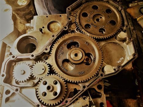
Helical teeth generate an axial thrust load that must be reacted by duplex thrust bearings or taper-roller bearing pairs; this adds cost and a failure mode that single-helical and industrial gear spur designs avoid. Double-helical (herringbone) layouts cancel the thrust but cost more and limit the supplier pool. The SMX ships in metric 5:1, 13:1, 20:1, 25:1 ratios — a wide selection that still leaves gaps when a non-standard ratio, fine-pitch module, or high helix angle is specified [S1]. Sealing is a real concern: enhanced seal options on input and output are sold as an upgrade for hostile environments, not as standard [S1]. Per-kW price runs higher than worm units in the same torque class, especially below 5 kNm, where worm gearing is typically the cheaper pick. Backlash is also wider than in harmonic reducer or precision planetary units, which rules out indexing and CNC servo applications.
Comparison: Helical vs Worm vs Planetary vs Cycloidal
The four-way selection matrix below lines up the most common parallel-shaft and offset choices against the criteria that drive a process-engineer spec. Helical units lead on efficiency and torque density; worm leads on cost and right-angle simplicity; planetary and cycloidal lead on backlash and stiffness. gear coupling selection on the input and output shafts shifts with each format because torque, misalignment tolerance, and backlash are not equivalent across the family. [S2]
Helical / worm / planetary / cycloidal on four criteria: efficiency, cost-per-kW, backlash, and shock-load tolerance. Helical: 95–98% per stage, mid cost, mid backlash, high shock load tolerance. Worm: 30–90% per stage, low cost, mid backlash, low shock load tolerance. Planetary: 95–97% per stage, high cost, low backlash, high shock load tolerance. Cycloidal: 90–95% per stage, high cost, low backlash, very high shock load tolerance. The helical row dominates general parallel-shaft service; the cycloidal and planetary rows win where backlash is the gate.
Selection Criteria, Sourcing, and Standards
For an SMX-class unit, the datasheet gives a clean spec set: torque above 10 kNm, input 0.36–287 kW, output 10–400 rpm, ratios 5:1 / 13:1 / 20:1 / 25:1 metric and 5:1 / 15:1 North American, with parallel and taper-bore output options [S1]. Cement-mill main gear drives push that envelope: forged-rim carburized steel gears to ISO-DIN 6 grade, electro-welded housings, and bearings sized for at least 100,000 hours full-load service [S2]. For buyers sourcing on price, Alibaba lists 100+ helical gear reducer suppliers with total revenue above US$100 million, dominated by Chinese OEMs such as Hzgear Sinodrive Co., Ltd (founded 1982, 101–200 employees) [S3][S4]. For lower ratios in the 5:1 / 15:1 range, sprag-clutch backstops are a standard option to prevent drive reversal, and rapid-response "off-the-shelf" availability is now common [S1].
Use Cases, Fit-Gates, and Known Failure Modes
Misfit gates: indexing/CNC servo (backlash), sub-1 kW right-angle drives (cost), and high-radial-misalignment chain drives (coupling selection). End-of-life signals to track: rising oil temperature past design value, vibration above acceptance band during reduced-load test, and seal oil leak at input or output [S2]. For installation sequence and run-in gates, the Helical Gear Reducer Installation: Foundation, Alignment, Lubrication, and Run-In reference lays out the bolt torque, shaft seating, and oil-fill checks. For cost-side trade-offs across reducer families, the RV Reducer TCO: Cost Drivers, 10-Year Spend Stack, and Spec Gates write-up gives a parallel benchmarking frame.
Trackable next signals: (1) confirm ISO-DIN 6 gear-grinding grade on the supplier MTC, (2) verify bearing L10h life ≥100,000 h at full load [S2], and (3) compare the supplier's seal-package listing against the actual dust/water/exposure rating before sign-off.