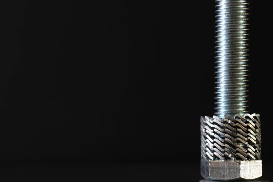
Helix angle mismatch is the first thing to check when a turned thread shows flank rake, chatter, or rapid insert wear, because a 1.5° error in tilt is enough to push the cutting edge out of the helix plane on anything steeper than a coarse pitch [S2]. The helix angle is not a single value for a given thread; it changes from the major diameter through the pitch diameter to the minor diameter, so the choice of reference diameter directly changes the tilt value written on the shim [S7].
In a turning setup, projecting the thread profile means aligning the insert's clearance face normal to the local helix, not to the spindle axis, which is the geometric reason for tilting the tool in the first place [S2]. This single adjustment controls chip flow, contact patch, and effective included angle, and it interacts with insert geometry, lead, and number of thread starts [S5].
Helix angle definition and why tilt is needed
The thread helix angle λ is defined by the relationship tan λ = lead / (π × D), where D is the chosen reference diameter and lead equals pitch for single-start threads [S5][S6]. Because the thread is a spiral, the cutting edge of a perfectly axial tool would contact the workpiece on one flank only, generating asymmetric load and rapid wear on the leading edge [S2]. Tilting the insert so its clearance face sits normal to the helix direction equalises the load on both flanks and reproduces the correct included angle at the cutting zone [S2].
The standard ER/EL 16 and 22-series threading insert holders ship with a 1.5° shim as the default setting, which is the tilt value that best matches common ISO metric threads in the M16 to M22 range on mild steel [S5]. For a 1.0 mm pitch M16 thread, the helix angle at the pitch diameter lands inside the 1.5° blue band on the shim diagram, while a 1.5 mm pitch M20 thread drifts toward 1.0° and a 2.0 mm pitch M20 climbs past 2.0°, requiring a non-standard shim [S5].
Pitch diameter vs major diameter for the calculation
For a quick shop-floor check, using the major diameter in tan λ = lead / (π × D) is acceptable and underestimates the true helix angle by roughly 10 to 15% on typical ISO threads [S5]. For a precise cut, the pitch diameter gives a value close to the angle the cutting edge actually sees, because the engaged surface of a V-thread sits between the crest and the root, nearer the pitch line [S5]. The helix angle is not constant across the thread depth: at the major diameter the angle is lowest, and at the minor diameter it is highest, because lead is fixed while the local circumference shrinks [S7].
A practical rule from thread turning guidance is to take the average of major and minor diameters as a one-step approximation of the pitch diameter, which lands within about 0.1° of the exact value for standard 60° ISO threads [S5]. For multi-start threads, lead = pitch × number of starts, and a 3-start thread with the same pitch triples the helix angle, so the same thread geometry can require a 3° to 4° tilt where a single-start would stay under 1.5° [S5].
Shim selection and insert holder geometry
Triangular threading inserts are mounted on shims (anvils) that set the tilt, and the catalog of shims for the ER/EL 16 and 22 families runs in 1° increments from -1.5° through 0.5°, 1.5°, 2.5°, 3.5° to +4.5°, with part-number suffixes matching the angle sign [S5]. Negative shim angles are used for the cross-handed combinations: a right-hand thread on a left-hand tool, or a left-hand thread on a right-hand tool [S5]. The 1.5° preset is the geometric mean of the available range and was chosen because most single-start metric and unified threads in the size band of common 16 mm and 22 mm inserts fall into that 1.0° to 2.0° window [S5].
For an exaggerated case, a multi-start thread with a 45° helix angle makes the geometry obvious: the insert must be perpendicular to the helix direction with the point on centre, otherwise the tool is partly turning and partly planing the flank, which is a textbook form-tool error [S2]. This is the same correction used for any form tool, and it is why lathe handbooks stop being accurate once the helix climbs past roughly 3° [S2].
Why a 1.5° error breaks the thread profile
Tilting the insert to better match the helix angle gives more clearance on the leading edge of the tool, which is required when cutting high-helix or left-handed threads on a standard right-handed setup [S2]. If the included angle is ground for an axial tool but the tool is then tilted, the effective included angle at the cut changes: a 60° point ground axially and tilted 3° produces an asymmetric profile with one flank at about 58.5° and the other at 61.5° on a 60° thread form, which is enough to fail a go/no-go ring gauge on the flank-angle criterion [S2]. The standard correction is to grind the included angle on the tilted tool so the projected profile lands at the nominal 60° (or 55° for BSW, 29° for ACME) in the plane normal to the helix [S2].
In practice this is the same compensation machinists apply when grinding a form tool for a tapered or curved surface, and it explains why experienced turners abandon commercial threading inserts for shop-made holders with a round carbide blank ground to the thread angle and indexed to the helix [S2]. For a buttress thread with a 5° / 50° asymmetric form, the tilt and the angle compensation are both non-trivial, and the tool is effectively a small form tool riding the helix [S2].
Application in thread rolling and modelling
In lathe thread rolling with knurling rollers, the helix angle match between the workpiece and the rollers is enforced by fixturing the rollers on a tilted axis, and the same tan λ = lead / (π × D) relation drives the setup [S3]. A mismatch here shows up as a spiral scoring pattern on the rolled flank rather than a uniform thread, and hardened tool steel rollers (typically D2 or M2 at 58 to 62 HRC) are required to survive the sliding contact [S3]. The tilt of the roller axis is set once per pitch-diameter combination and is not adjustable on the fly, which makes the pre-machined helix calculation more important than in single-point turning [S3].
For CAD modelling of threads, the helix cut feature in packages such as Alibre uses a profile orientation flag, and switching from the default to the Normal orientation projects the 2D thread profile onto the plane normal to the helix, which is the same geometric correction described above for the physical insert [S4]. The CAD "Normal" option is the software equivalent of tilting the insert in the holder, and it produces a more correct flank angle on the swept thread body, especially for pitches above 1.5 mm where the helix angle exceeds 2° on typical bolt sizes [S4].
Helix angle in dental implant thread design (a comparison case)
The same helix-angle variable appears in dental implant design, where a 0.8 mm pitch, 1.6 mm pitch, 2.4 mm pitch, double-threaded and triple-threaded implant geometries were modelled in finite element analysis to study micromotion in D2, D3 and D4 bone [S1]. Vertical micromotion is positively correlated with thread pitch and helix angle, and negatively correlated with compactness, while the effect of pitch and helix angle on stability is limited in D2 (dense) bone and amplified in D3 and D4 (softer) bone [S1]. The clinical threshold is roughly 100 to 150 µm of micromotion during healing; above 150 to 200 µm, osseointegration fails [S1].
This is a useful contrast: in machining, a high helix angle is desirable for chip flow and is corrected by tilting the insert; in an endosseous implant, a high helix angle is undesirable because it increases micromotion under load, so designers go the opposite way and pick compact, low-pitch single-start threads for soft bone [S1]. The geometric variable is identical, but the engineering optimum is inverted between the two fields.
Decision rules and limits of the tilt adjustment

Use the major diameter for a quick check on whether a standard 1.5° shim is in band; use the pitch diameter when the calculated value is within 0.3° of a shim boundary, or when the thread is multi-start, fine-pitch, or larger than M24 [S5]. For a 60° ISO thread, the helix angle at the pitch diameter stays below 4.5° for most standard pitches up to about 6 mm on diameters up to M64, which is why the shim catalog stops at +4.5° [S5]. Outside that range, a custom-tilted tool holder or a shop-ground form tool is the practical answer, not a thicker shim [S2].
The tilt adjustment cannot fix a wrong included angle, a wrong nose radius, or a tool mounted off centre; it only re-projects the existing tool geometry onto the helix-normal plane [S2]. If chatter appears after a tilt change, the cause is usually that the new clearance angle has gone negative on the trailing edge, which means the shim is over-tilted for that pitch-diameter combination, and stepping back to the next-lower shim (for example from +2.5° to +1.5°) restores a positive rake on both flanks [S2][S5]. For an engineering cross-check on similar geometric tolerancing, see the taper-lock bush angle specification at Taper Lock Bush Angle and Taper Ratio Explained, and for the wider context of how a small angular error drives a profile rejection, the thread-engagement rule on Ex d Cable Gland Thread Engagement shows the same 5°-class sensitivity on a different thread form.
The next trackable signals for thread-turning tilt practice are the rolling out of catalog shims beyond +4.5° for large-pitch oil-country threads, and the appearance of CAM packages that auto-suggest a shim part number from the entered pitch and diameter, replacing the manual table lookup that is still standard in 2026 [S5]. For related thread-form background relevant to industrial valve stem and bonnet connections, the same 1.5° default applies to NPT and BSPT single-start tapered threads, where the helix angle at the pitch diameter sits inside the standard shim band for sizes up to 2 inches.
The underlying component specifications are covered under angle grinder, and tilt sensor.