
The taper lock bush system uses a 1:12 taper ratio, which works out to an included angle of approximately 4.76°, and that shallow geometry is what makes the joint self-locking once the fixing screws are torqued home [S1][S2].
That 1:12 ratio is the same cone family found on lathe spindles and Morse tapers, scaled up to a removable, torque-transmitting shaft-hub joint that millwrights fit daily on conveyors, fans, pumps and chain drives [S1].
What the 1:12 Ratio Actually Means in Practice
A 1:12 taper means the diameter changes by 1 unit for every 12 units of axial length, so a 2517 bush with a 44 mm length shows roughly 3.67 mm of radial draw-in from large end to small end [S1]. When the fixing screws are tightened, the bush is pulled axially into the hub taper; the longitudinal split then lets the outer surface contract slightly, which generates the radial clamping force on the shaft [S1][S5]. The taper geometry converts screw torque into radial compression, so a mismatched bore will not seat correctly and holding strength drops sharply [S5].
The shallow angle, around 4.76° included on metric bushes, is deliberately below the self-release angle of steel-on-steel, which is why a properly seated bush stays put without relying purely on screw pre-load [S1]. One practitioner on a machining forum separately described a roughly 6° included angle on the imperial split-taper variants he remachined, which reflects the older Browning/Gates-style split-taper family, not the 1:12 metric Taper Lock system [S4]. The two families are not interchangeable: the metric Taper Lock and the inch split-taper bushings use different tapers, different keyways, and different screw patterns [S5][S6].
Reading the 1008 to 5050 Size Series
Every metric Taper Lock bush carries a four-digit code in which the first two digits approximate the maximum bore in tenths of a millimetre and the last two digits give the bush length in millimetres, so a 2517 takes up to about 65 mm bore and is 44 mm long, while a 5050 covers up to about 125 mm bore at 127 mm length [S1]. The full range runs from 1008 (≈10 mm bore, 20.5 mm long) up to 5050, with 18 standard sizes between them, all dimensionally interchangeable across manufacturers because the series is built to BS 4235 Part 2 [S1].
This interchangeability is one of the practical reasons the system survived: a 2517 bush from Fenner, Dunlop, SKF, Rexnord, Gates or TB Wood's will drop into any compliant hub stamped 2517, which keeps spares inventory manageable on multi-vendor sites [S1]. One large-bore caveat: bore sizes marked with an asterisk in supplier tables, such as the 3525 at 100 mm bore or 4030 at 115 mm bore, are only available in the marked bush sizes, so a 3525* bore is not a stock item on a 3535 [S3].
Slip Torque and the Case for a Key

Published slip-torque tables show how rapidly the joint rating climbs with both bush size and bore diameter, which is the easiest way to size a hub against an application's worst-case torque [S3]. A 2517 bush on a 60 mm bore delivers about 670 Nm of average slip torque, while a 5050 bush on a 125 mm bore reaches roughly 7,370 Nm on a steel hub rated 600 N/mm², almost an order of magnitude higher [S3]. On a 3020 bush the slip torque scales from 520 Nm at 38 mm bore to 1,300 Nm at 75 mm bore on the same 600 N/mm² steel hub, so underkeying the bore alone can halve the joint capacity [S3].
Friction is not enough for sustained industrial loading, which is why a parallel key seated in matching keyways is mandatory for anything beyond low-torque or intermittent service [S1]. With a key fitted, the slip tendency shifts from the shaft-bush interface to the bush-hub interface, and the limiting torque there is governed by the ratio of bush outer diameter to bore, not by friction on the shaft [S3]. For reference, a typical 2517 has an OD of about 65 mm against a 60 mm bore, giving a hub-slip torque roughly proportional to that ratio, which is why the hub material table matters as much as the bush size [S3].
Hub Material, Minimum Diameter and Standards
Minimum hub outside diameters for a 3020 bush range from 132 mm on 600 N/mm² steel to 160 mm on 180 N/mm² cast iron, a swing of more than 20% that reflects the burst stress the wedging action puts on the hub rim [S3]. Across the size range, a 1008 needs only 47 mm hub OD on 600 N/mm² steel but 62 mm on weak cast iron, while a 5050 needs 213 mm on the same steel grade and 240 mm on weak iron [S3]. Bespoke hubs drilled, tapped and taper-bored for Taper Lock bushes must hit these minimums or the radial and circumferential stresses from the wedging mechanism will crack the rim [S3].
The dimensional series is governed by BS 4235 Part 2, which is what makes bushes from different makers physically interchangeable, while the taper geometry itself is a de facto standard rather than a separately numbered ISO clause [S1]. For larger or higher-torque builds, double split-taper and QD (Quick Disconnect) bushes are the two common alternatives, and they use different mounting methods and alignment procedures, so a hub drilled for one will not accept the others [S6]. On a retrofit, the safer approach is to copy the existing bush code off the hub face, since guessing across families is the single most common cause of an unusable bush on the shop floor [S1].
Comparison: 1:12 Taper Lock vs QD vs Double Split Taper
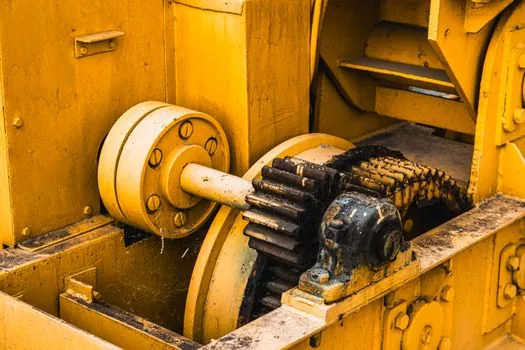
Taper Lock, QD and double split-taper bushes all do the same job, which is clamping a hub to a shaft, but they diverge sharply on geometry, mounting and torque range [S6]. The Taper Lock family uses a 1:12 ratio (≈4.76° included) with two fixing screws, suits bores from roughly 10 mm up to 125 mm, and depends on a parallel key for sustained torque, making it the workhorse of light-to-medium industrial drives [S1][S3]. QD bushes use a steeper taper with three or four flange screws, mount faster on a production line, and cover similar bore ranges but with a different hub-bore preparation, so a QD hub will not accept a Taper Lock bush and vice versa [S6].
Double split-taper bushes add a second longitudinal slot to give more uniform radial compression, are common on heavier conveyor and mining pulleys, and typically need higher assembly torque values, with the S2 split-taper variant specifying 840 in-lbs of wrench torque at installation against only 348 in-lbs on a Q1 [S5]. For selection, three criteria cut through the marketing: hub OD available (small bosses rule out QD on a retrofit), shaft bore range (Taper Lock covers the widest stock range), and whether the site already runs one family (carrying three sizes across three systems is a maintenance trap on any taper bush inventory) [S5][S6].
Installation Sequence and Common Failure Modes
Correct installation starts with a dry, oil-free bore and hub mating surface, screws lightly placed in the hub threads, the key dropped into the shaft keyway first, and the assembly slid on as a single unit before any torque is applied [S3]. Screw torque is then increased in even alternate passes, which is what draws the bush into the hub taper and the bush onto the shaft in one controlled motion, instead of letting the hub bind on the shaft before the bush has seated [S3][S1].
Most field failures trace back to one of three causes: oil or anti-seize left on the taper surfaces, which kills the friction grip and lets the bush walk out under load; a missing or undersized key, which forces the joint to rely on friction alone; or a hub bored undersize for the chosen bush series, which cracks under the wedging stress [S1][S3]. A reuse inspection before fitting a bush to a new pulley catches thread stretch, brinelled bores and corrosion pitting that would otherwise trash the shaft, and it is cheap insurance given that a 2517 costs a fraction of the downtime a sheared shaft causes on a construction machinery and equipment drive [S3].
Where the 1:12 Geometry Fits and Where It Does Not
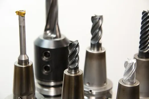
The 1:12 metric Taper Lock geometry is the right call for most fixed-speed industrial drives, conveyor pulleys, fan and pump couplings, and chain sprockets, where a removable, hand-tool-driven joint is the priority [S1][S2]. It is the wrong call on reversing or shock-loaded flywheels, where a tangential key pair is the proper geometry to resist bidirectional torque and where a standard parallel key on a Taper Lock bush will rattle loose within hours, so the joint design has to change rather than the bush size [S7].
For routine replacement, the 1008 to 5050 series covers the vast majority of common shaft sizes, and the same four-digit code stamped on the hub face is the only number a millwright needs to walk into a store and walk out with a drop-in bush [S1]. Watch two signals over the next 12 months: any update to BS 4235 Part 2, which would ripple through every supplier's catalogue at once, and the slow migration of small QD adoption into the light-conveyor segment, which would erode Taper Lock's lowest end of the range rather than the mid-size 2517 to 3535 workhorse [S1][S6].
The underlying component specifications are covered under angle grinder.
For related coverage, see Reuse or Scrap: Inspecting a Taper Bush Before It Goes on a New Pulley.