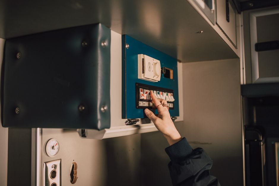
A hinge-interlock safety switch with one normally-closed safety output, slow-action break-before-make contacts, and a die-cast aluminum body installs against an M5 fastener torqued to 4.0 Nm, with a 12 mm shaft and PG11 / 1/2 in NPT cable entries per Comepi's SDM2K61X11 and SP2K72X11 datasheets [S1][S2][S5].
Two reference part numbers — SDM2K61X11 (lever hinge, three 1/2 in NPT entries, 0.7 lb) and SP2K72X11 (hollow-shaft hinge, 12 mm × 20 mm shaft, plastic body, 0.2 lb) — frame the mechanical envelope most maintenance planners will encounter on existing guards [S1][S2]. Acceptance requires a documented risk assessment, competent installer sign-off, and verification that the guard cannot be defeated with a second actuator [S5].
Pre-Install Risk Assessment and Switch Type Selection
ISO 14119 requires installation of every interlock switch to follow a written application risk assessment, carried out by competent personnel only [S5]. Hinge interlocks (SDM2K61X11, SP2K72X11) suit hinged doors where the pivot itself signals guard position; tongue-actuated interlocks fit sliding or removable guards where the actuator enters a separate key slot [S1][S2][S3]. Fortress AmStop 4 (ATSTOP024) ships as 2 N.C. / 1 N.O. with tongue actuator, used where higher-category safety output counts are mandatory [S3]. RS PRO's catalog currently lists 21 AmStop/Schmersal/ABB/SICK/Omron-coded options with 142 actuator variants and 39 product-type entries, indicating the breadth of typology an installer must filter before ordering [S4]. For a deeper classification map, see the Safety Interlock Switch Types and Classifications: ISO 14119 Map, Spec Bands, and companion article.
Mechanical Mounting: Bolt Torque, Shaft Diameter, and Cable Entry
M5 mounting bolts are the standard fastener for interlock switch bodies, with 4.0 Nm tightening torque specified to guarantee reliable fixing, and the bolts must be locked against loosening after installation [S5]. On the SP2K72X11 hollow-shaft variant, the actuator shaft measures 12 mm diameter × 20 mm length and drops into a standard door-hinge pin bore; mismatched shafts will bind the cam and prevent full contact transfer [S2]. The lever-hinge SDM2K61X11 body provides three 1/2 in NPT cable entries, die-cast aluminum housing, and a plastic head, weighing 0.7 lb — adequate for industrial panels but requiring sealing glands rated to the enclosure IP code [S1]. Cable entry on the SP2K72X11 is one PG11 with a 1/2 in NPT adapter, and the body is all-plastic at 0.2 lb, restricting it to lower-impact zones [S2].
Contact Topology, Switching Action, and Safety Output Wiring
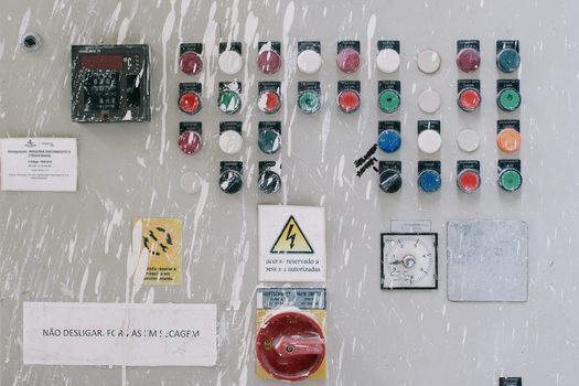
Both reference switches are slow-action break-before-make, with one N.C. safety output — the configuration demanded by ISO 14119 category 1 and category 3 circuits when paired with a monitored safety relay [S1][S2]. Slow-action (positive-opening) contacts guarantee mechanical separation independent of contact wear or contamination, unlike snap-action contacts which can momentarily reclose under vibration. Higher-density requirements are met by the AmStop 4 ATSTOP024 at 2 N.C. / 1 N.O., which adds a normally-open auxiliary for status feedback to the PLC without using a safety input [S3]. Wiring must route through a safety relay or a safety PLC input certified to the category calculated in the risk assessment; using the N.C. pair directly into a standard PLC input defeats the redundant-channel requirement and is a recurring audit finding.
Actuator Alignment, Cam Travel, and Mechanical Verification
After bolt torque, the second most common failure mode is insufficient cam travel: the actuator must rotate the internal cam through the full angle specified on the datasheet before the N.C. contact opens, otherwise the safety output stays closed while the guard is partially open. Maintenance engineers should insert a 1 mm feeler gauge between guard and frame at the latch point and confirm the switch trips before the gap exceeds 2 mm — a rule derived from the typical 3 mm to 14.5 mm actuator insertion depths catalogued across RS PRO's 142 actuator variants [S4]. The hollow-shaft design on SP2K72X11 simplifies alignment because the shaft is the hinge pin, removing a separate actuator-to-cam adjustment step that the lever-hinge SDM2K61X11 still requires [S1][S2]. After alignment, cycle the guard 25 times under power and confirm the safety relay status LED indicates positive-opening on every cycle.
Guard Door Defeat Prevention and Tamper Resistance
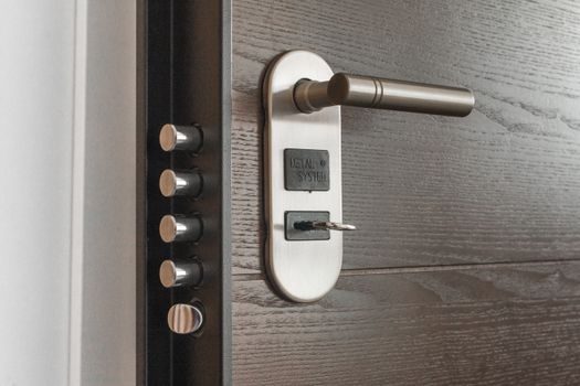
ISO 14119 mandates that the switch be mounted so it cannot be defeated using a second actuator, easily bypassed tools, or simple substitution — a clause that eliminates low-coding-level switches from category 3/4 applications [S5]. Hinge interlocks score well here because the actuator is integral to the hinge pin; the most common defeat attempt — wedging the door open — is detectable by the safety relay as a contact that fails to reclose on next cycle. Where higher coding levels are required, tongue-actuated switches with unique-coded actuators (such as the AmStop 4 line at 2 N.C. / 1 N.O.) become mandatory, and the actuator must be permanently fixed to the guard to prevent swap-out [S3]. Periodic functional testing — typically every 6 to 12 months depending on duty cycle and environment — is the only way to catch contact welding, cam wear, or actuator loosening before they become a defeat path.
Acceptance Test, Documentation, and When to Replace
Commissioning a hinge interlock switch ends with three documented checks: (1) measure contact resistance on each N.C. pair in the closed state (expect <50 mΩ for new silver-alloy contacts, replace above 200 mΩ); (2) verify positive-opening with an ohmmeter while manually cycling the guard through 10 full open/close operations, recording the angle at which the N.C. opens; (3) confirm the safety relay or safety-PLC input drops out within the response time declared on its datasheet [S5]. If any of the three checks fails, replace rather than repair — interlock switches are field-serviceable only for cable entry and actuator wear parts; contact sets are factory-sealed. Cross-reference the Safety Interlock Switch Types and Classifications guide when specifying a replacement to confirm the new part matches the original ISO 14119 coding level and category.
Trackable signals for the next maintenance window: (a) functional-test log showing cycle count per guard, since most hinge switches are rated for 1 million mechanical operations; (b) safety-relay diagnostic counters for any contact bounce events captured on cycle >500,000; (c) inventory parity between installed hinge-switch part numbers and the spares list, given the broad 39-product-type catalog currently distributed by RS [S4].
The underlying component specifications are covered under safety interlock switch, linear guide, and crossed roller guide.