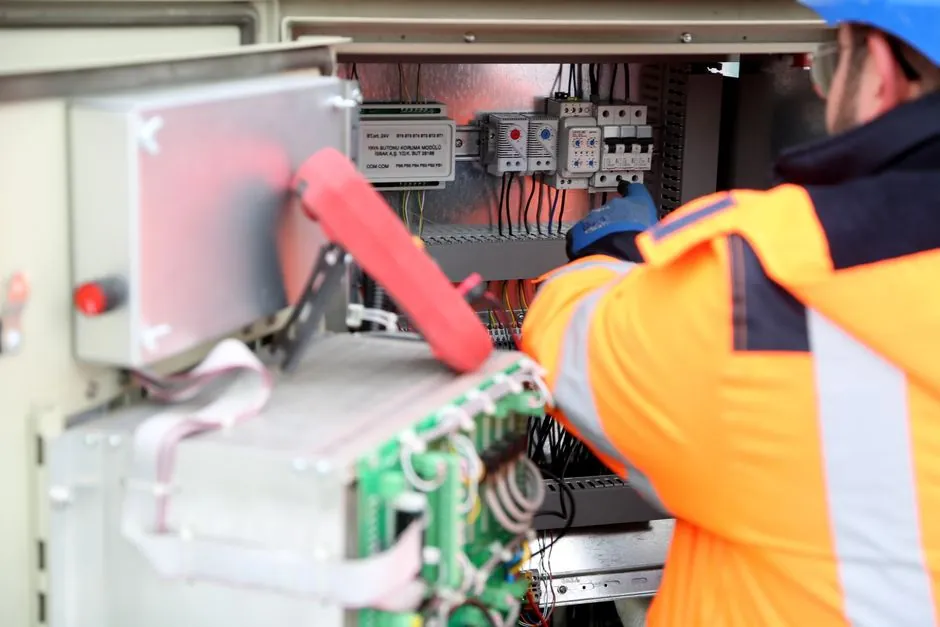
A microprocessor protection relay samples CT and VT secondary quantities, converts them into digital values, and executes protection logic in software rather than springs, disks, or fixed analogue circuits [S4].
For motor feeders, transformers, generators, feeders, and other industrial equipment, selection starts with the protected object and system voltage, then proceeds to sensor inputs, required functions, setting ranges, communications, event records, environmental limits, and commissioning support [S4].
Define the protection duty before comparing relay families
Protection relays detect abnormal voltage, current, and frequency conditions and can disconnect the affected section of an electrical system [S1]. They are divided into two principal categories: digital relays built around microprocessors, and electromechanical relays that change state through electromagnetic and mechanical forces [S1].
A microprocessor relay is suited to applications requiring multiple protection, control, metering, and communications functions in one device [S3]. Relevant function numbers include ANSI 50 and 51 for overcurrent, 50N and 51N for earth fault, 67 for directional overcurrent, 87 for differential, 21 for distance, and 49 for thermal replica [S4].
For a motor application, the relay may need thermal overload protection, phase-loss detection, earth-fault protection, and undervoltage or voltage-unbalance functions. Dedicated guidance on motor protection undervoltage and voltage unbalance functions can be used alongside the general selection process. The correct starting point is the equipment being protected, not the number of functions advertised by the relay.
Build the selection around voltage, CTs, VTs, and settings
The first engineering checks are system voltage, protected-equipment identity, and CT or VT inputs [S4]. A relay connected to the wrong nominal voltage or transformer ratio can misjudge operating current, voltage thresholds, and coordination with upstream or downstream devices.
Microprocessor-based relays commonly sample approximately 8 to 80 times per electrical cycle, with accuracy depending on the anti-alias filter and analog-to-digital converter [S4]. The relay must therefore be matched to the instrument-transformer output, including ratio, secondary current or voltage, accuracy class, frequency range, and burden.
Do not select from nominal current alone. Confirm the required setting range, pickup values, time delays, reset characteristics, and multiple setting groups [S4]. For a motor, the thermal model must match the machine's starting behavior and permissible overload characteristics, while phase-current protection must coordinate with the contactor, circuit breaker, and upstream feeder protection.
A useful review sequence is: 1) system voltage, 2) protected equipment, 3) CT/VT inputs, 4) protection functions, 5) setting range, 6) communications, 7) event and fault recording, 8) environmental requirements, 9) applicable compliance, and 10) testing and commissioning requirements [S4].
Compare the principal relay types by operating capability

Electromechanical relays remain in service, but they generally perform only one or two functions [S1]. Microprocessor relays analyze several electrical parameters, record and transmit monitoring data, and can combine functions that would otherwise require separate devices [S1][S3].
Use communications and records as engineering requirements
Event records and fault recording can expose the sequence that led to a trip, while remote monitoring supports condition assessment and operational control [S4]. These features are not decorative. They determine whether engineers can reconstruct a disturbance, retrieve a setting group, or identify a failed protection element without opening the panel.
Protocol selection must follow the plant architecture. A relay may need to connect to SCADA, an engineering workstation, or another relay through an industrial communications network [S4]. The procurement specification should name the required protocol, port type, baud rate, data points, alarm behavior, and time-synchronization method rather than stating only that the relay must support communications.
Open architecture is a relevant development direction in relay protection because it can improve interoperability between protection devices and external systems [S5]. However, protocol support does not by itself prove end-to-end compatibility. Test the relay against the actual engineering tool, supervisory system, gateway, and point list before release.
Check environmental, compliance, and commissioning requirements
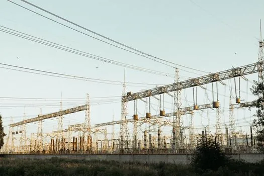
Environmental verification is a separate selection gate, covering operating temperature, humidity, vibration, electromagnetic compatibility, and enclosure conditions appropriate to the installation [S4]. These requirements matter because a relay with correct protection logic can still be unsuitable for a hot panel, electrically noisy motor room, or outdoor substation.
The purchasing file should identify the required IEC or IEEE compliance for the exact relay category, country, installation, and application [S4]. Compliance references must be confirmed against the manufacturer's current declarations and certificates; a generic statement that a product is IEC or IEEE compliant is not adequate for approval.
Commissioning requirements should be settled before purchase. Confirm that the relay supports the required test methods, setting export, event download, alarm injection, breaker trip simulation, and firmware maintenance [S4]. The technical comparison in MV versus LV motor protection relay pricing and specification boundaries is particularly relevant when the candidate relay is being evaluated for different motor-circuit voltage classes.
Account for diagnostics, maintenance, and failure consequences
Self-diagnostics and self-testing are listed among the operational benefits of microprocessor relaying, alongside sequence-of-events records and oscillography [S3]. These features do not remove the need for periodic testing, but they can expose internal degradation and improve fault investigation [S3].
The business comparison should include more than purchase price. A microprocessor relay may require less routine mechanical maintenance and can provide more operating information, but it introduces software configuration, communication configuration, and end-of-life management considerations [S2]. Firmware, passwords, setting backups, and compatibility with plant tools should therefore be treated as part of the asset record.
Do not choose the multifunction microprocessor relay for every application by default. A simple, limited electromechanical or thermal relay can be adequate when only one protection function is required, local indication is sufficient, and no records, communications, or coordinated settings are needed [S1]. The stronger engineering case for microprocessor equipment appears when the installation needs several coordinated functions, fault records, remote access, or a unified protection platform.
Make the final acceptance a shortlist of verified capabilities
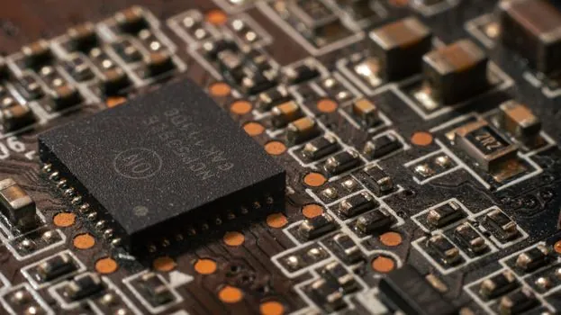
A shortlist should retain only relays that pass four gates: electrical compatibility, protection adequacy, operational integration, and serviceability. Electrical compatibility requires the correct system voltage and CT/VT inputs. Protection adequacy requires the required ANSI functions, validated setting ranges, and proper coordination. Operational integration requires the specified protocol, event records, and engineering-tool access. Serviceability requires environmental qualification, test support, and maintainable configuration records [S4].
Before purchase order release, request three concrete demonstrations from each manufacturer: inject the worst-case fault current and show pickup and trip timing, retrieve a stored event and oscillogram, and complete a settings backup and restore through the supported engineering tool. These tests expose interface, mapping, timing, and documentation gaps that a general capability statement cannot resolve.
Track two procurement signals for every candidate: confirmed CT/VT input ranges with their required accuracy, and the exact setting range for each protection function. If either is still marked as subject to confirmation, the relay is not ready for a protection-coordination decision.