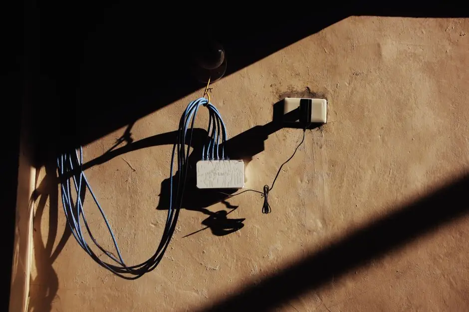
A USB-to-Ethernet adapter gives a legacy control PC or embedded device an RJ45 connection when the machine has no native Ethernet port, with the adapter connected through USB and a Cat5e or Cat6 patch cable [S1].
The practical choice depends on the machine’s USB interface, available drivers, electrical environment, and required throughput. A direct USB adapter is simpler than a wireless bridge, while a dock can also provide display, power, and peripheral connections.
USB-to-Ethernet adapter architecture
The RJ45 socket on an Ethernet adapter provides the physical connection to a switch, router, modem, or local area network. The adapter itself contains the interface electronics that allow a USB host to communicate through that wired network path [S2].
A practical connection consists of three parts: the legacy device, the USB-to-Ethernet adapter, and an Ethernet patch cable.
This arrangement is intended for a device that needs a wired network connection but lacks a usable RJ45 socket. It is not a conversion path for every legacy serial, fieldbus, or proprietary control interface. The adapter adds Ethernet connectivity; it does not automatically translate serial protocols, PLC addressing, or machine-control signals into Ethernet protocols.
Choosing the adapter for the legacy machine
Start with the machine’s physical USB inventory rather than the adapter’s headline speed. The documented laptop example had one HDMI connector, one USB 3.0 Type-C port, and two USB 2.0 Type-A ports, while the proposed solution was a USB Ethernet adapter [S4]. That interface mix makes port count and USB generation relevant to selection.
Compare available options on four criteria: native interface fit, network speed, operating-system support, and enclosure requirements. A Type-A adapter suits a machine with USB Type-A ports, while a Type-C adapter suits a Type-C host. The driver must support the legacy operating system and the USB chipset used by the adapter.
For an industrial installation, also check whether the machine’s USB port is for data or only service, power, or maintenance. Confirm the adapter’s supported operating-temperature range, enclosure rating, grounding method, indicator functions, and available mounting arrangement. A consumer adapter may be adequate for a bench test but unsuitable for a cabinet where temperature, vibration, electromagnetic interference, or accidental unplugging governs reliability.
USB adapter versus wireless bridge

A USB-to-Ethernet adapter preserves a wired connection from the machine to the network switch. The alternative documented for a home lab used a Wi-Fi range extender to convert a wireless link into Ethernet output, then routed that connection through an OPNsense router to another SOHO router configured as an access point [S3].
The comparison below separates the two architectures across connection medium, cable requirement, typical benefit, and main constraint.
The bridge approach is useful where a direct Ethernet connection cannot be installed and new network drops cannot be added [S3]. It also suits machines without Wi-Fi radio hardware. Its weaker point is that the machine’s traffic ultimately depends on a wireless hop, even though the final device connection uses Ethernet.
Adapter selection for legacy industrial PCs
A legacy machine with no Ethernet port is a good candidate for a USB Ethernet adapter when it already has a data-capable USB port and the network link is short, deterministic, and easy to inspect.
It is a poor fit for a hard real-time control loop whose timing was validated over a specific interface, or for a device whose USB port is disabled for security reasons. A bridge is also unsuitable where radio interference is severe or where the network specification requires a continuously physical wired path from the machine to the switch.
For industrial communications, protocol compatibility must be checked separately from physical connectivity. A machine using EtherNet/IP, PROFINET, Modbus TCP, or another industrial Ethernet protocol needs software and driver support for that protocol as well as Ethernet connectivity. The plug-in network icon is evidence of a link, not proof that a PLC project, supervisory system, or fieldbus stack will communicate correctly.
Wiring, configuration, and commissioning checks
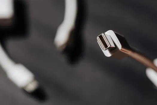
A standard Ethernet port has 8 pins, and its plastic retention clip secures the cable connector in the socket [S2].
Commission the connection in a defined sequence. First, verify that the legacy machine detects the adapter and installs the required driver. Second, connect the cable and confirm that the adapter and switch report link activity. Third, assign or obtain the required IP configuration. Fourth, test the intended traffic path rather than relying only on general internet access.
Common checks include the adapter’s USB enumeration, the network adapter entry in the operating system, link or activity indicators, correct address configuration, gateway and subnet settings, and firewall policy. Dell’s hardware reference treats Ethernet links through the lens of connector type, cable standards, adapter types, LED diagnostics, and device-specific connection planning [S2].
Security and reliability boundaries
A wired link removes the machine from the radio path, but it does not provide automatic network isolation. A legacy machine connected through a USB adapter can still reach every network permitted by its address, routes, services, and firewall policy. Segment it through a dedicated switch or VLAN when the control network must remain separate from business or guest traffic. [S3]
The related decision framework in Plant Network Isolation: Securing Connected Machines Without Air-Gapping covers segmentation controls for connected equipment that cannot be physically air-gapped. For an adapter-based retrofit, the relevant controls include switch port assignment, VLAN membership, firewall rules, and monitored switch links.
Wireless bridging adds another reliability boundary. The documented home-lab arrangement was chosen partly because network-heavy services could congest a shared Wi-Fi link, while devices lacking good antennas could maintain unstable connections at distance [S3]. For production use, a direct USB-to-Ethernet path is therefore easier to diagnose: the USB adapter and patch cable can be replaced or inspected independently of radio conditions.
Selecting the retrofit that matches the installation
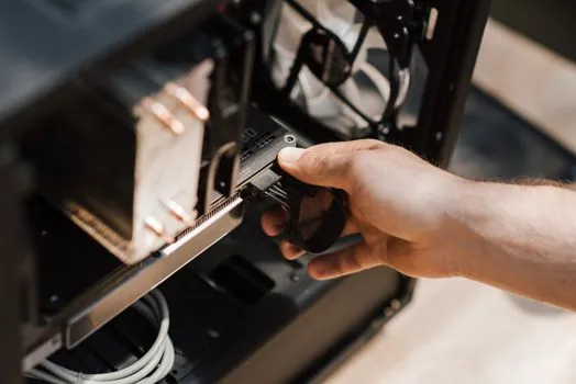
For a legacy machine with a working USB data port, a USB-to-Ethernet adapter plus Cat5e or Cat6 patch cable is the direct solution [S1]. Select the connector type, speed class, driver, and industrial enclosure requirements before installation.
Use a Wi-Fi-to-Ethernet bridge only when installing a new network drop is impractical and the wireless path has acceptable signal quality. Track adapter identification, link establishment, assigned address, and successful exchange of the machine’s required protocol traffic. Those four checks provide a clear acceptance record for the retrofit.