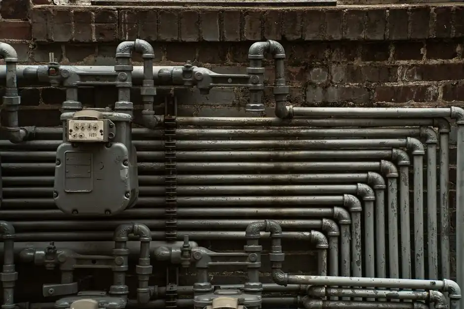
Pipeline diameter is the single geometric decision that ties conveying velocity, pressure drop, and solids loading ratio together, and it must be solved iteratively rather than picked from a catalog [S1][S3].
For a given throughput, the bore falls out of the continuity equation Q = v × A once the designer commits to a conveying mode and a target gas velocity, with the 4,000-8,000 fpm band for dilute phase and lower velocities for dense phase [S4][S5].
Start With the Material, Not the Pipe
Bulk density, particle size distribution, moisture, and abrasiveness are the inputs that constrain every downstream number, and guessing at this stage is the most common root cause of systems that fail to meet rated capacity [S1][S4]. Engineers treat bulk density in lb/ft³ as the primary energy variable for particle entrainment, then layer in shape, fines fraction, and stickiness for powders used in food, pharma, and specialty chemicals [S1]. For abrasive duties (glass batch, coal ash, mineral concentrates) the sizing goal shifts to survival: run at the lowest velocity that still suspends the particle, so pipe walls and rotary-valve seats do not erode prematurely [S1][S4].
Two of the four key parameters an engineer needs on hand are the solid loading ratio (mass of solids per mass of conveying gas) and the saltation velocity, which is the minimum gas velocity that keeps particles suspended in horizontal flow [S4]. Operating below saltation is the textbook condition for line plug; published working bands sit at roughly 3,000-6,000 fpm for light powders and 4,000-8,000 fpm for granules or pellets [S4].
Choose the Conveying Mode Before Picking a Bore
Dilute-phase conveying suspends particles fully in a high-velocity stream (commonly 4,000-8,000 fpm) and suits non-abrasive, free-flowing materials; dense-phase conveying moves higher solids concentration as slugs, plugs, or dunes at lower velocity and is the default for fragile or abrasive products [S4][S5]. Mode choice dictates the velocity band you feed into the continuity equation, and that velocity is what sets the cross-sectional area A for a given volumetric airflow Q [S4]. For a rough sizing target, designers aim gas velocity at 20-30% above the calculated saltation velocity to keep dilute-phase transport stable through transients and startups [S4].
Selection also tracks material character: dilute phase is typically simpler and steadier over long distances with light bulk solids, while dense phase is favored where lower velocity cuts pipeline wear and product degradation, though not every bulk solid behaves predictably in dense phase and pilot testing is often required before commercial commitment [S5].
Apply the Continuity Equation and Check Pressure Drop
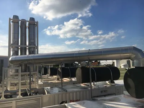
The mechanical step is straightforward: with required mass throughput (lb/hr or kg/hr), bulk density, and a target gas velocity, convert to volumetric airflow Q, then solve D = √(4Q / (πv)) for the internal bore [S4]. Pipe diameter is one of three levers (with airflow and pressure) that determine whether material moves smoothly or the line chokes before it ever runs [S4]. After a bore candidate is fixed, total pressure drop is summed from straight-pipe friction (Darcy–Weisbach), bend and fitting equivalent lengths, and the vertical lift term, and that total is what sizes the blower or vacuum pump [S4][S2].
Two more couplings matter. Pickup velocity at the feed point runs slightly above saltation velocity to guarantee clean line startup [S4]. And the receiver / filter-separator at the discharge has to be matched to the same airflow the line was sized for, otherwise the back-pressure shifts the operating point off design [S5].
What Happens When the Diameter Is Wrong
A bore that is too small for the duty raises air and material velocity, increases pressure loss, loads the blower harder, accelerates particle impact, and pushes abrasive or fragile products into degradation or capacity-limited operation [S3]. A bore that is too large drops gas velocity below the suspension threshold, particles settle, dunes form, and the line plugs, often within hours of running at design throughput [S3][S5]. The failure modes are symmetric: small bore destroys equipment, large bore destroys uptime [S1][S3].
Pipeline diameter influences ten coupled variables at once: air velocity, material conveying velocity, pressure or vacuum requirement, system resistance, transfer capacity, flow stability, particle degradation, pipe and bend wear, blockage risk, and total air volume [S3]. Treating bore as an isolated pipe-choice is the most common sizing error; the correct framing is bore-as-a-function-of-airflow, loading, route, bends, and receiver [S3].
Routing, Bends, and Vertical Lift as Hidden Diameter Drivers
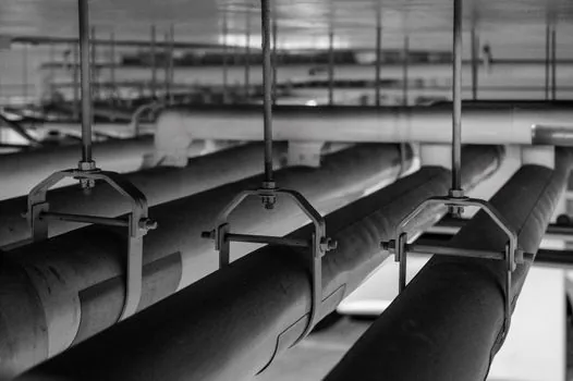
Horizontal run length, number of bends, and total vertical lift each add to the pressure-drop budget and therefore shift the minimum practical bore upward for the same throughput [S2][S4]. Long conveying distances and multi-bend routes are the cases where dilute-phase positive-pressure systems dominate, because the higher pressure capability of a positive blower can sustain velocity to the receiver [S5]. Vacuum systems, by contrast, are preferred when pickup is from multiple points and dust containment matters, since leakage tends to flow inward rather than outward [S5].
Conveying mode is also a routing decision: the slug or plug flow of dense phase tolerates vertical lift and longer horizontal runs better than dilute phase at the same bore, provided the material is amenable to dense-phase behavior [S5]. For related mechanical-handling hardware, hollow-flight screw conveyors handle the heating or cooling duty that often sits upstream of a pneumatic line, and they are sized on a similar mass-flow / bulk-density basis.
Standards, Safety, and Verification
There is no single ISO or ASME standard that fixes a pipe diameter for a pneumatic conveying duty; sizing is a calculation per ISO 2859-1 / engineering-judgment activity anchored to material testing and the Darcy–Weisbach / Rizk-style saltation correlations implemented in tools such as the Calcimator pneumatic conveying calculator [S6]. The Rizk-style correlation used for saltation scales with pipe diameter, the ratio of particle density to air density, and particle size raised to a small power, which is why bore must be re-evaluated whenever the bulk solid changes [S6].
Equipment on the air-moving and isolation side falls under the Machinery Directive 2006/42/EC for CE marking, and the technical-file expectations in CE technical file for machinery: what Annex VII actually requires in 2026 are the documentation hook for the design assumptions you used to pick that diameter. A pneumatic conveying system sized on the methods above, with documented material data and a verified pressure-drop total, is the audit-ready baseline. For more on the actuation side, see the pneumatic actuator and pneumatic cylinder references.
Specification Comparison: Dilute vs Dense Phase at the Same Throughput
For a fixed mass flow, the two modes land on different bores because they target different gas velocities: dilute phase at 4,000-8,000 fpm yields a smaller bore, higher velocity, lower pressure; dense phase below saltation yields a larger bore, lower velocity, higher pressure, and a slug/dune flow pattern [S4][S5]. Abrasive or fragile products score dense phase as the better fit because wall wear scales with velocity cubed in many erosion models, while free-flowing pellets and non-abrasive minerals score dilute phase for simplicity and steady flow [S1][S4][S5]. The bore is the same equation in both cases, only the target v in Q = v × A changes.
Trackable signals for a new design: (1) re-verify the saltation velocity against the actual bulk solid before committing bore, because the Rizk-style correlation is sensitive to particle density ratio and size [S6]; (2) run a pressure-drop total including every bend and the full vertical lift before ordering the blower, since the air mover is sized off this number, not off the diameter alone [S4][S2].