
A hydraulic unloading valve is a pressure-sensitive, pilot-operated control valve that opens a full-bore path to reservoir once downstream pressure reaches a preset cut-out, typically set 50 to 200 PSI below maximum working pressure [S1].
Once tripped, pump discharge collapses to a few bar, a check valve traps pressurized fluid in the accumulator or actuator, and the motor coasts at roughly 10 to 20 percent of loaded power draw, dropping bulk oil temperature 15 to 25 degrees C versus a relief-only dump [S2].
How the Cut-Out and Cut-In Pressure Band Works
The valve sits in the main pressure line between the pump and the system, and a spring-loaded spool or poppet is held in the loading position by spring force until system pressure is fed through a pilot line to the opposite end of the element [S1]. When pilot force exceeds spring force, the spool shifts and opens a full-flow path to tank, at which point the pump sees almost no resistance and discharge pressure drops to just enough to push oil through the return line [S2].
Re-loading is governed by a pressure differential or hysteresis band between cut-out and cut-in, and a narrow 10 percent band gives stable pressure but forces short recharge intervals, while a wider 20 to 30 percent band stores more fluid per cycle at the cost of larger pressure swing, with most press and clamp circuits settling on 15 to 20 percent [S2]. Cut-out and cut-in must be set with reference to ISO 4413:2010 maximum pressure limits, which requires designers to size components against both peak pressure and bulk fluid temperature when the band is defined [S5].
Accumulator Circuits: The Default Home for an Unloading Valve
Accumulator systems are the most common application: the pump charges the accumulator until pressure reaches the cut-out, the valve trips and unloads the pump, and the accumulator then supplies fluid on demand until pressure bleeds back to cut-in [S2]. In a holding application, that interval can stretch to minutes or hours, which is why unloading valves are described as essential for systems with long holding cycles such as clamping, braking, and standby pressure [S4].
The trade-off is that the pressure differential directly sets usable accumulator volume, and a poorly sized band shows up as rapid cut-in/cut-out cycling, audible chatter around setpoint, and oil temperature climbing during idle, all classic field symptoms that unloading is missing or unstable rather than a relief valve simply leaking [S4]. For broader HPU thermal design context, see this walkthrough of HPU cooler heat rejection sizing, since oil temperature is the single most visible indicator of unloading health.
Hi-Lo Dual-Pump Circuits: Unloading as the Crossover Switch
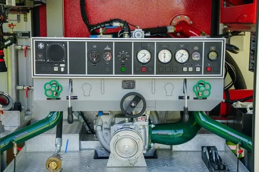
A hi-lo circuit pairs a large displacement pump for high flow at low pressure with a small pump for high pressure at low flow, and the unloading valve is the crossover element: at low pressure both pumps deliver flow and the actuator moves fast, then when resistance builds and pressure hits the crossover point the valve dumps the large pump to tank and only the small pump continues to press at full force [S2]. Compared to a single large pump sized for the high-force work stroke, this layout typically cuts motor size by 30 to 40 percent and is the standard architecture for injection molding machines, presses, and compactor drives [S2].
For safety relief sizing on the high-pressure leg, the underlying principles and sizing rules are covered in the safety relief valve reference, and hi-lo circuits still require a properly set relief on the small-pump leg to handle over-pressure events such as a blocked cylinder port.
Unloading Valve vs. Pressure Relief Valve: A Side-by-Side
Relief valves are sized as safety devices, normally closed during the work cycle, and only open on overpressure to bleed flow while the pump continues to deliver at full pressure; unloading valves are efficiency devices, designed to open repeatedly on every standby, holding, or transition cycle, and they drop pump discharge to near tank pressure [S1][S4]. That is why a relief valve forced to act as an unloader shows up in the field as a hot tank, a motor that sounds loaded during idle, and accumulator charging cycles that are far more frequent than the design intent [S4].
A relief valve also belongs on every HPU as the overpressure safety device and is governed by the same ISO 4413:2010 envelope, so an efficient circuit typically uses both: a pressure relief valve sized for maximum system pressure as a safety cap, and an unloading valve sized for full pump flow at near-zero pressure drop to dump flow during normal standby. Power consumption in the unloaded state is widely reported to fall to 10 to 20 percent of loaded operation, and well-engineered unloading circuits are documented to cut motor load by over 80 percent during idle cycles on accumulator holding and hi-lo press systems [S2][S4].
Selection Criteria: Pilot Type, Hysteresis, and Contamination Tolerance
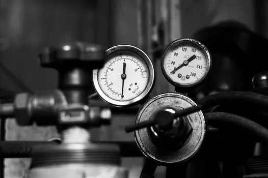
Selection starts with maximum pump flow at cut-out and the required pressure band, since the valve must pass full pump flow at a delta-P of only a few bar once tripped, not the small bleed flow a relief valve handles [S2][S4]. Pilot type matters because externally piloted, vented-to-tank designs track downstream pressure cleanly, while internally piloted units are simpler but can be confused by pump ripple and back-pressure, which is one root cause of chatter [S5].
Hysteresis control should be specified rather than assumed, because real-world vibration, contamination, and temperature swing demand engineered hysteresis rather than cheap fitment, and a stable band in the 15 to 20 percent range is the usual field starting point for press and clamp duty [S2][S4]. Fluid cleanliness targets should follow the valve maker's ISO 4406 code, typically 18/16/13 or cleaner for pilot-operated poppet valves, and contamination is the dominant root cause of unstable cut-in/cut-out cycling seen on installed units [S5].
Failure Modes, Diagnostic Symptoms, and Field Limits
The five field symptoms that point to a missing or unstable unloading valve are oil temperature climbing during idle or holding, a motor that audibly stays loaded while the machine waits, accumulator charging cycles that are far more frequent than the design interval, pressure ripple or chatter around setpoint, and a hi-lo press losing efficiency at the approach-to-press transition [S4]. A 30-second circuit check covers three questions: is there an accumulator plus check valve that actually holds pressure, does the pump still run at high outlet pressure during idle, and is there a dedicated pump-to-tank path triggered by downstream pressure [S4].
An unloading valve is not a safety blow-off and must not be used as a substitute for a correctly set relief valve or for the correct accumulator pre-charge, both of which have to be right before any unloading valve can do its job [S4]. Pilot-operated relief valves, which are a related architecture, do not begin to open until the system reaches roughly 90 percent of full pressure, which protects efficiency by limiting bypass flow, and the same pilot logic is what gives a quality unloading valve its decisive cut-out [S5]. Trackable signals for the next design review are the cut-out/cut-in pressure data logger trace over a full machine cycle, the steady-state oil temperature at the reservoir after 30 minutes of idle, and the motor kilowatt reading at idle versus loaded, all of which give a clean before/after number once an unloading valve is added or re-tuned.
For component-level specifications, see function generator, and construction machinery and equipment.