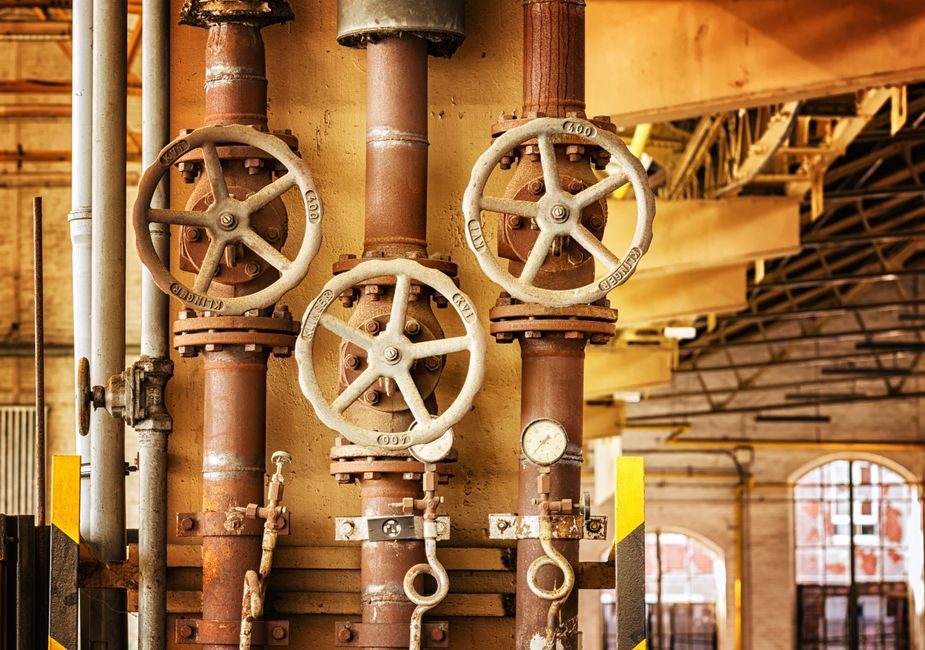
A hydraulic accumulator is a pressure vessel that traps a charge of pre-charged nitrogen behind a piston, bladder, or diaphragm; when system pressure rises above the pre-charge, hydraulic fluid flows in, compressing the gas and storing energy that can be released on demand to dampen pulsation, absorb pressure spikes, or act as an emergency reserve.
A hydraulic valve, by contrast, is a flow-control element: directional-control, pressure-relief, flow-control, check, or proportional valves shape where the fluid goes, how much passes per unit time, and at what pressure differential it is allowed to move.
For a buyer mapping a circuit, the rule of thumb from the 2026 supplier landscape is: an accumulator manages energy and pressure stability; a valve manages flow path and pressure setpoint. They are complementary components, not substitutes, and both are catalogued in nearly every Chinese hydraulic OEM's product line including Ningbo Fenghua GO GO Automatic (founded July 2014) and QT Hydraulic (Shanghai) Stock Co., Ltd. [S1][S3].
Operating Principle and Core Functions
An accumulator's working volume is split by an elastomer or piston into a gas side (pre-charged to 60-90% of system working pressure, with bladder and piston types most common in 2026 OEM catalogues) and a fluid side connected to the hydraulic line. Energy stored follows the gas law PV^n = constant, with n ≈ 1.4 for adiabatic fast cycles and n = 1.0 for isothermal slow leak-down; usable fluid volume is typically 30-60% of the total physical volume depending on pre-charge ratio [S2].
A hydraulic valve's function is described by its port count, spool position count, and actuation method. A 4/3 directional-control valve with solenoid or proportional actuation, for example, has 4 ports (P, T, A, B) and 3 spool positions, and its flow capacity is rated in L/min at a stated pressure drop, typically 350 bar system pressure in industrial mobile and stationary hydraulics [S3].
Energy storage capacity of an accumulator is commonly given in litres of effective volume, with 1-50 L being the most common industrial band; valve flow capacity is given in L/min, with 20-500 L/min covering most proportional and servo-valve industrial use cases [S2][S3].
Type Comparison: Accumulator Variants
Bladder accumulators (the dominant mobile-equipment type) deliver fast response (typically under 25 ms) and tolerate 350 bar working pressure with standard nitrile bladders; piston accumulators (used in heavy industrial and mining) handle higher flows and pressures up to 700 bar but are larger per litre of stored volume; diaphragm accumulators cover the small-volume 0.1-4 L range for compact pulsation dampers [S2].
Comparing the three on decision criteria: bladder types win on response time and cost per unit volume up to 50 L; piston types win on flow handling and high-pressure rating; diaphragm types win on footprint and weight below 4 L. Pre-charge gas is dry nitrogen at 99.95% purity in all three, with the pre-charge port normally a 5/8"-18 UNF or M28 schrader-type valve [S2].
Selection rule from the 2026 supplier data: bladder for shock and pulsation damping in mobile and press circuits, piston for high-flow energy recovery and large stationary reservoirs, diaphragm for compact OEM machine tools and lubrication skids [S2].
Type Comparison: Valve Variants
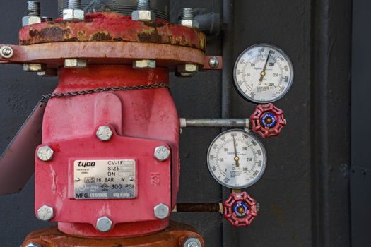
Directional-control valves (DCV) are catalogued by spool symbol such as 4/2, 4/3, and 6/3, and are normally rated to 315-350 bar with flows of 60-500 L/min in the CETOP/NG6 to NG25 size bands. Pressure-relief and pressure-reducing valves are spring-loaded and set within 50-350 bar standard ranges, with remote-pilot and vented options for unloading [S3].
Proportional valves add a continuously variable solenoid current (typically PWM at 100-200 Hz, 4-20 mA, or 0-10 V command) over a standard DCV body, giving closed-loop pressure or flow control. Servo valves are the high-end sub-millisecond response variant (≤ 1 ms step response, ±2% hysteresis) used on machine tools and aerospace test rigs. Check, flow-control, and counterbalance valves are simpler poppet or spool elements sized by orifice and cracking pressure [S3].
By mounting standard, the most common 2026 industrial band is CETOP 3 (NG6) up to CETOP 8 (NG25), with subplate or threaded porting; mobile equipment still uses the SAE 2-bolt and 4-bolt flange pattern on the same pressure class [S3].
Selection Criteria and Decision Logic
If the problem is pressure spike, pulsation, or emergency back-up: specify an accumulator, sized as V_effective = (Q × t) / (P_max/P_min - 1) for pulsation damping or by pump flow × response time for emergency [S2].
If the problem is flow path, direction, or pressure setpoint: specify a valve, sized by required L/min at ΔP = 10 bar across the spool (the standard catalogue reference condition), with margin on peak flow of at least 1.25× [S3].
The two components are routinely specified together: a press circuit, for example, uses a hydraulic cylinder driven by a directional-control valve, with a bladder accumulator on the return line to absorb shock at end-of-stroke; a hydraulic motor loop on a mobile crane typically pairs a counterbalance valve with a piston accumulator sized for thermal-expansion relief and braking reserve [S2][S3].
Materials and fluid compatibility: accumulators use carbon-steel bodies with nitrile (NBR) or fluoroelastomer (FKM) bladders, suitable for mineral oils to ISO VG 46-68; valves use cast iron or forged steel bodies with hardened steel spools, and the same fluid spec applies. Stainless steel 316 is required for pharmaceutical, food-grade, and offshore subsea circuits per NACE MR0175 (2025-08) for H2S service.
Standards, Ratings, and Certification Markings
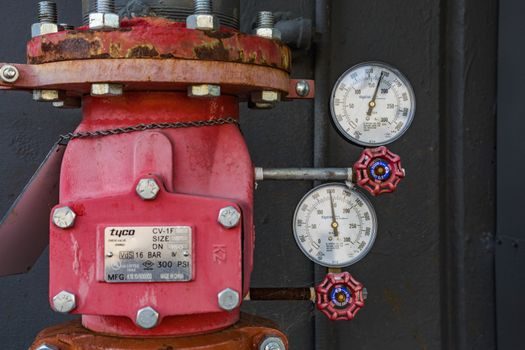
Accumulators are pressure vessels and fall under the Pressure Equipment Directive 2014/68/EU in the EU and ASME BPVC Section VIII Div. 1 in North America; they are CE-marked with category I-IV depending on PS × V product, and PED-stamped with a notified-body number above the Category III threshold [S2].
Valves used in process and marine service follow ISO 4401 (mounting surfaces), ISO 7241 (quick-couplings), and API 6D for pipeline isolation. ATEX 2014/34/EU and IECEx certification are mandatory for Group II Category 2 G/D (zone 1/21) when an accumulator or valve is installed in a hazardous-area hydraulic power pack on a refinery or chemical plant.
Both components carry a nameplate giving serial number, PS (max allowable pressure), TS (min/max temperature, typically -20 °C to +80 °C for NBR bladder accumulators and -40 °C to +120 °C for FKM variants), and year of manufacture; Chinese OEM nameplates in the 2026 catalogues follow the same GB/T 13384 packaging and GB/T 14039 fluid cleanliness coding, with most factory-tested to ISO 4406 18/16/13 cleanliness minimum [S1][S3].
Sourcing Logic: Cluster, Maker Map, and Lead Time
China's accumulator supply chain in 2026 is anchored in Ningbo, Wuxi, and Shanghai: smaller bladder units (0.5-10 L) are dominated by 50-100 mid-tier makers serving mobile machinery, while piston and large-volume types (10-200 L) come from a handful of integrated steel-fabrication factories including subsidiaries serving the Caterpillar and Sany supply chain [S1][S2].
Valve sourcing in 2026 is led by Shanghai (QT Hydraulic and roughly 30-40 proportional-valve specialists), Hangzhou (DCV and stack-valve cluster), and Beijing (servo-valve R&D); for non-critical mobile circuits a 4/3 manual or solenoid DCV in NG6 size lists in the US$35-90 FOB Shanghai band, while proportional and servo variants run US$200-2,000 depending on flow and feedback package [S3].
A 10 L bladder accumulator from a Tier-2 Ningbo maker in 2026 lists at roughly US$80-180 FOB Ningbo, with a 30-day lead time off-shelf and 60 days for non-standard ports. For a closer look at how Chinese hydraulic component factories benchmark against international buyers' spec lists, see this hydraulic motor buying guide, which uses the same Ningbo/Shanghai supplier geography [S1][S3].
Limitations, Failure Modes, and Common Pitfalls
Accumulator failure modes ranked by frequency in 2026 service data: gas pre-charge loss (slow leak through the valve, -0.5 bar/year typical), bladder rupture from fluid contamination or over-pressure, and external corrosion of the shell if the protective coating is damaged. A loss of pre-charge over 10% is the standard re-charge trigger [S2].
ISO 4406 18/16/13 minimum cleanliness at fill, with on-line filtration to NAS 6 (ISO 4406 19/17/14), is the standard countermeasure [S3].
Cross-spec trap: a hydraulic pump cannot substitute for an accumulator for energy storage; a pump delivers continuous flow at its displacement × speed, while an accumulator delivers a short high-flow burst equal to its usable volume. A check valve cannot substitute for a pressure-relief valve: a check valve is passive (cracks at a low ΔP and does not reseat against system pressure), whereas a relief valve is adjustable and reseats at a defined set pressure. Misreading the difference is one of the most common specification errors in low-cost hydraulic panels [S3].
Next signal to track: ASEM Shanghai (Hydraulic & Pneumatic Asia) in November 2026 is the primary venue where Ningbo, Wuxi, and Shanghai makers release new bladder and piston accumulator lines, and where the major valve OEMs (QT Hydraulic, KRACHT) typically launch proportional-valve refreshes; expect refreshed NG6-NG10 proportional spools and 50 L class high-pressure piston accumulators as the most visible 2026 spec additions [S1][S3].