
Hydraulic cylinder installation is a 10-step procedure dominated by prep, depressurization, alignment, mechanical mounting, and air bleeding, with 50% of field failures traced to skipped purge steps and mis-torqued fasteners [S1][S2].
Specifying engineers and maintenance crews share the same fault tree: missing PPE, neglected side-load limits on the piston rod, and venting ports installed face-down, which trap air pockets and damage the rod guide [S3][S6]. A clean, dry work area is non-negotiable, since ISO 4406 contamination control cannot be retrofitted at the mounting pad [S1][S2].
Pre-Installation Prep and Safety Lockout
Before any spanner touches a port, the hydraulic cylinder must be depressurized, the pump locked out, and shut-off valves closed, with the circuit bled to zero bar to remove stored energy [S2][S4]. Required PPE is the standard five-item set: safety goggles or glasses, steel-toe boots, gloves, ear protection, and a hard hat [S2][S4]. The work area must be clean and dry, because particulate ingress during installation is the leading root cause of seal failure in the first 500 hours of service [S1][S6].
Pre-mounting checks include inspecting the delivery for completeness and transport damage, removing protective sealing plugs and cover plates, and verifying the part number against the order confirmation and assembly drawing [S3]. Hydraulic pipes must be flushed and all components (bearings, clevis pins, spherical rod eyes) pre-greased before they enter the hydraulic envelope, since dry assembly scores chrome-plated rods within three stroke cycles [S2][S4].
Mechanical Mounting and Side-Load Discipline
Cylinders with rigid mounting (such as side-lug or foot-mount configurations) must be installed free of stress, with thermal expansion joints incorporated at the mount elements for long-stroke units [S3]. The permissible side load on the piston rod is the single most violated specification in field retrofits, and exceeding it causes guide bushing galling, rod scoring, and premature seal extrusion [S3]. For movable mounts, sufficient clearance between the spherical rod eye and the clevis bracket must be left for the designed pivot and tilt range, typically a minimum of 5% of stroke length, to prevent binding at full extension [S3].
The standard mechanical sequence covers eight steps: (1) adjust installation stroke length to the pre-check value from the assembly drawing; (2) match new end-of-stroke damping settings to the old cylinder; (3) verify alignment of connection holes; (4) lift the cylinder into position; (5) torque mounting fasteners; (6) remove protective plugs; (7) connect hydraulic hoses; (8) remove lifting slings and supports [S2][S4]. For large loader cylinders that resist hand extension, mechanics use a come-along or the machine's own hydraulic lever at idle creep speed to align the lower pin, avoiding any hose connection until the rod end is mechanically pinned [S5].
Fastener Torque per VDI 2230 at Strength Class 10.9
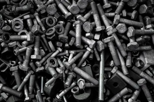
Cylinder head screws must be minimum strength class 10.9, torqued per VDI 2230 at a friction coefficient of 0.14, with values from M5 at 9.5 Nm up to M24 at 1136 Nm [S3]. The published VDI 2230 torque table gives: M5 = 9.5 Nm, M6 = 16.5 Nm, M8 = 40 Nm, M10 = 79 Nm, M12 = 137 Nm, M16 = 338 Nm, M20 = 661 Nm, and M24 = 1136 Nm, which applies to metric mounting hardware only [S3].
Pressure port screw connections default to DIN 3852 Part 2, Forms A and B, unless the engineering drawing specifies otherwise, with soft-seal screw-in studs recommended over tapered threads for easier re-sealing [S3]. Tightening torques for these BSP-style ports differ between standard screw connections and swivel banjo bolt configurations, ranging from 18 Nm at G 1/8 to 700 Nm at G 1-1/2 banjo fittings [S3]. When counter-holding the piston rod during fitting work, use a hook wrench per DIN 1810 with a round pin, never an adjustable wrench on the rod, since chrome damage from a slipped jaw voids the rod warranty [S3].
Venting, Bleeding, and Air-Pocket Prevention
Hydraulic cylinders and pressure intensifiers must be installed with venting ports at the top to allow air to rise and escape during initial pressurization, a geometric requirement that the assembly drawing typically does not explicitly call out but is enforced by every OEM manual [S3]. Most units ship with venting screws on both sides, with vent bores sized to accept standard measuring coupling ports, which doubles as the bleeding interface [S3]. Air trapped in the cap-end or rod-end chamber causes spongy stroke response, jerky creep at low speed, and accelerated seal wear from adiabatic compression heating.
The bleeding procedure runs the cylinder through 3 to 5 full stroke cycles at low pressure with the reservoir at working level, cracking each vent screw until solid oil appears with no foam, then re-tightening per the port torque table [S2][S4]. A field test for completeness is a 10-minute dwell at full extension with no visible piston drift, indicating that dissolved air has been purged and the hydraulic cylinder is ready for rated load [S2][S4]. For paired cylinders in a curl or lift circuit, the cylinder with the least resistance moves first when the valve is cracked, so alignment must be checked with the bucket or attachment free to settle before both sides are pinned [S5].
Mounting Configuration Comparison for Common Cylinder Types

The four dominant mounting styles for hydraulic cylinders each carry distinct alignment and clearance requirements, summarized below for selection during spec-out and field retrofit: [S1]
1) Clevis mount (pinned both ends): most forgiving on side load, allows ±5° pivot swing at the rod eye, but requires matched pin diameters and retaining hardware; preferred for agricultural and mobile equipment [S1][S5]. 2) Side-lug mount (rigid): zero pivot tolerance, demands stress-free alignment within 0.5 mm/m parallelism, and is restricted to short-stroke push applications; failure mode is lug cracking at the bore [S3]. 3) Foot mount (rigid base): used for inline press work, requires dowel pins to absorb reaction loads, and tolerates higher side loads than side-lug but less than clevis [S3]. 4) Trunnion mount (pinned at barrel midpoint): handles high side loads and oscillating motion, common in heavy mobile and injection-molding applications, with trunnion bearing grease zerks requiring 1 shot every 500 hours [S3]. For application guidance on the broader hydraulic actuator family, mounting style drives rod bearing selection, while the hydraulic cylinder duty cycle determines seal compound choice.
When NOT to Install and Common Failure Modes
Do not install a hydraulic cylinder if the rod shows chrome pitting deeper than 0.05 mm, straightness exceeds 0.1 mm per 300 mm of stroke, or any seal gland has visible extrusion cuts [S6]. Bent or scored rods cause seal damage on the first stroke and will repeat the failure within 50 hours, regardless of installation quality [S5].
Three failure modes dominate field returns. First, dry assembly on a newly repaired cylinder with no grease at the clevis pin or spherical eye binds under load and snaps the rod at the thread runout, the exact failure pattern reported in the field case where a fully extended cylinder snapped "almost smooth straight across" when side-loaded during a spillway dig [S5]. Second, mis-torqued port fittings at G 1/2 or larger leak at 50% of rated pressure, with the published 90 Nm standard versus 120 Nm banjo figure being the most common error on European-spec hoses [S3]. Third, end-of-stroke damping misadjustment causes metal-to-metal impact that dents the cap-end plug and cracks the gland within 200 hours of cycling [S2][S4]. For mobile-equipment systems where the hydraulic motor drives the same pump that feeds the lift cylinder, paired commissioning is covered in a hydraulic pump installation field guide, while directional control valve setup and torque follows a separate hydraulic valve installation procedure.
Standards, Tooling, and What to Verify Before Re-pressurization
Compliance touches ISO 4413 (general hydraulic fluid power rules), ISO 4406 (fluid cleanliness), and the manufacturer's own DIN 3852 port geometry standard for connection threads [S3]. Relief valves must never be set above the cylinder's maximum rated pressure, and the equipment nameplate rating is the hard ceiling, not the pump's nominal output [S2][S4].
A 30-minute monitored run at full pressure with no external leakage, no rod drift, and stable reservoir temperature within ±5°C of ambient confirms the installation is ready for production service [S2][S4]. For integrated system commissioning where the cylinder is one element of a larger hydraulic circuit, the next gate is full-machine function testing against the OEM acceptance protocol.