
Hydraulic valves are the control core of any fluid power circuit, regulating pressure, flow rate, and flow direction so that cylinders, motors, and hydraulic actuators operate within safe force and speed envelopes [S1][S2]. Globally, the symbol language and functional boundaries are unified by ISO 1219 and the NFPA T2 / ANSI B93.9 series, with industrial builds typically rated between 200 bar and 700 bar [S4][S7].
Selection mistakes in 2025-2026 are still dominated by three failure modes: undersized relief valves, mis-porting between ISO 6149 and SAE J514 standards, and ignoring the 10-20% pressure-rating headroom rule published in mainstream supplier guidance [S1][S5]. This article lays out the current functional taxonomy, the dominant sub-types per family, and the spec gates that matter on a purchase order.
Three-family functional taxonomy: directional, pressure, flow
ISO 1219 and NFPA T2 define the functional boundary of every hydraulic valve as one of three control functions: directional, pressure, or flow, and that classification carries through to the schematic symbol [S7][S3]. Directional control valves (DCVs) start, stop, or redirect fluid between actuator ports; pressure control valves cap, reduce, sequence, counterbalance, or unload system pressure; flow control valves meter actuator speed by throttling a variable orifice or by holding a constant differential across a compensator spool [S1][S2][S3].
Within each family, sub-type choice is driven by duty cycle and cleanliness class. Directional valves ship as 2-position or 3-position spool types, as poppet designs for zero-leak duty, and as rotary or solenoid variants for compact manifolds [S3][S5]. Pressure valves split into relief, reducing, sequence, counterbalance, and unloading; flow valves split into fixed orifice, adjustable, pressure-compensated, and temperature-compensated designs, with priority valves used where one branch must always be fed [S2][S4].
Directional control valves: spool vs poppet, and actuation hierarchy
Direct-acting solenoid DCVs are limited by the magnetic force a coil can produce, so the practical ceiling for direct solenoid switching sits in the low hundreds of bar with modest flow; pilot-operated DCVs use a solenoid to shift a small pilot stage, which then moves the main spool with full system pressure behind it [S4][S8]. Spool valves dominate general-purpose industrial manifolds because they tolerate bi-directional flow, while poppet valves are preferred where internal leakage must stay near zero, such as in hose-burst and load-holding service [S3][S9].
Actuation choices stack from manual levers, through mechanical cams and pedals, to pilot-hydraulic, solenoid, and proportional-electronic, with the latter enabling closed-loop position and velocity control via PLC feedback [S8][S10]. A practical 2026 envelope for industrial DCVs: 350 bar maximum pressure, flow up to 300 L/min, port sizes from 1/4" to 1" in ISO 6149 or SAE J514 thread forms [S5].
Pressure control valves: relief, reducing, sequence, counterbalance
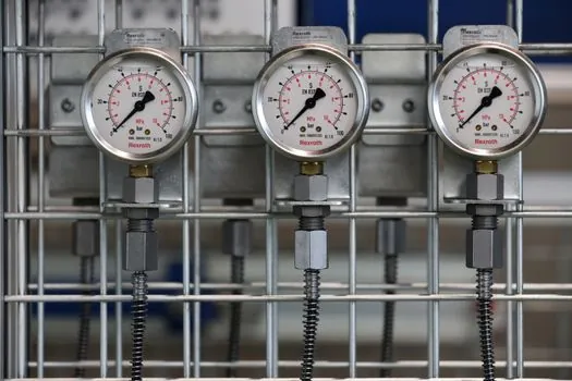
Relief valves cap maximum system pressure to protect hoses, actuators, and pumps; they are normally closed and open only when set pressure is exceeded, and their cracking-to-full-lift differential determines how cleanly the system holds setpoint under transient loads [S1][S2]. Pressure-reducing valves feed a downstream branch at a fixed lower pressure regardless of upstream swings, and sequence valves use a pressure signal to enable the next actuator in a programmed order [S1][S2].
Counterbalance valves are a specialised pressure device that holds a vertical or over-running load against back-pressure, preventing uncontrolled descent if a hose ruptures, and are therefore widely specified on cranes, aerial work platforms, and excavator booms [S3][S9]. Industrial pressure valves in 2026 supplier catalogues reach 420 bar, with stainless-steel bodies for corrosive service, NBR / Viton / polyurethane seals, and an operating temperature band of -40 to +120 deg C on standard builds [S5].
Flow control valves: throttle, compensated, priority
Throttle valves adjust flow by varying the cross-sectional area of the flow path, which the manufacturer literature explains via Bernoulli's principle; reducing the orifice increases fluid velocity and thus changes flow rate at a given pressure differential [S2][S4]. Fixed orifices, the simplest form, are drilled passages used in series with a pump to set a baseline flow, while adjustable orifices add a needle or spool for trim [S4].
Pressure-compensated flow valves combine a variable orifice with a spring-loaded compensator spool, holding volumetric flow constant across a wide load-pressure range so actuator speed remains steady on lifting and lowering strokes [S1][S2][S4]. A further refinement is temperature compensation, which corrects orifice drift when the fluid warms and viscosity falls; standard industrial flow valves sit in the 5-100 L/min band, 315 bar max, with port sizes between 1/4" and 1/2" [S5].
Proportional, servo, and cartridge logic elements
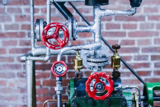
Proportional and servo valves close the loop electronically, accepting a variable current or PWM signal and producing a proportional spool displacement, which is what enables modern excavator load-sensing, injection-moulding closed-loop pressure control, and aerospace flight-control hydraulics [S5][S10]. Proportional units typically run at 350 bar and up to 250 L/min, with 0-70 deg C media limits, and they require matched electronic amplifiers with dither and ramp functions to keep hysteresis in check [S5].
Cartridge-style logic elements, governed by ISO 7368 for cavity dimensions, are screwed into a manifold block and combine with cover plates that carry the pilot logic, allowing high-density circuits that previously would have required stacked sandwich valves [S3]. The same cartridge family covers both DCV and pressure functions, which is why a 2026 mobile-machine architecture can collapse dozens of lines into a single monoblock or sectional manifold. For a deeper dive into the upstream pump side that feeds these valves, see the hydraulic pump spec map.
Selection gates: pressure headroom, ports, response, materials
Rated pressure must exceed maximum working pressure by 10-20% to give margin for transients, pump ripple, and cold-start viscosity spikes; ignoring this rule is the most common cause of seat and seal failure cited in supplier troubleshooting notes [S1][S5]. Port standards must match on both sides of the interface, with ISO 6149 metric threads and SAE J514 (JIC 37 deg flare) inch threads being the two dominant families, and mixing them is a known cause of cracked fittings on commissioning day [S5][S7].
Response time, leakage, and contamination tolerance are the other three gates. Solenoid valves for high-speed production machinery are typically specified below 100 ms step response, and internal leakage is generally held below 0.1 mL/min at test pressure [S5]. Media viscosity and ambient temperature drive seal choice, with NBR for mineral oil at -20 to +80 deg C, Viton for high-temperature or synthetic fluids, and polyurethane or PTFE for water-glycol and low-leakage service; a similar trade-off shows up when selecting construction machinery and equipment for cold-climate sites. Cleanliness targets in modern systems sit at ISO 4406 18/16/13 or better, which forces the matching of filter beta ratios to the valve maker's data sheet [S5].
Comparison: four valve families against decision criteria

Directional control valves deliver the highest nominal flow (up to 300 L/min) at moderate pressure (350 bar) and the widest actuation choice, making them the default for general-purpose machine builders. Pressure control valves reach the highest pressure class (up to 420 bar) and the lowest leakage, which is why they dominate safety circuits and load-holding. Flow control valves trade flow capacity (5-100 L/min) for speed stability through pressure or temperature compensation, which is essential on long-stroke cylinders where a simple throttle would change speed with load. [S5]
Proportional and servo valves sacrifice some maximum pressure headroom and add electronics, but they unlock closed-loop force, position, and velocity control that on-off valves cannot deliver. For a fuller total-cost view that pairs these valves with the pumps feeding them, the hydraulic pump TCO breakdown shows where energy recovery and load-sensing recoup proportional-valve premiums.
Applicable standards and sourcing checkpoints
Symbol and circuit conventions follow ISO 1219, with NFPA T2 / ANSI B93.9 serving the North American market; port threads are governed by ISO 6149 (metric) and SAE J514 (inch), and cartridge cavities by ISO 7368 [S3][S5][S7]. Material and pressure-bearing rules are typically anchored to national pressure-equipment codes, while safety functions such as counterbalance and hose-burst valves are integrated into machinery directives rather than free-standing valve standards [S3][S9].
Trackable signals for the next sourcing cycle: (1) supplier data sheets citing ISO 4406 cleanliness targets alongside ISO 7368 cavity codes, (2) relief-valve cracking pressure tolerances stated as a percentage rather than a fixed bar value, and (3) cross-references between ISO 1219 symbols and NFPA T2 symbols in the same catalogue page. Together these three signals separate current 2026-grade catalogues from legacy PDFs that have not been refreshed since the 2014-2017 standard cycle.
For the relevant spec sheets and selection criteria, see hydraulic valve.