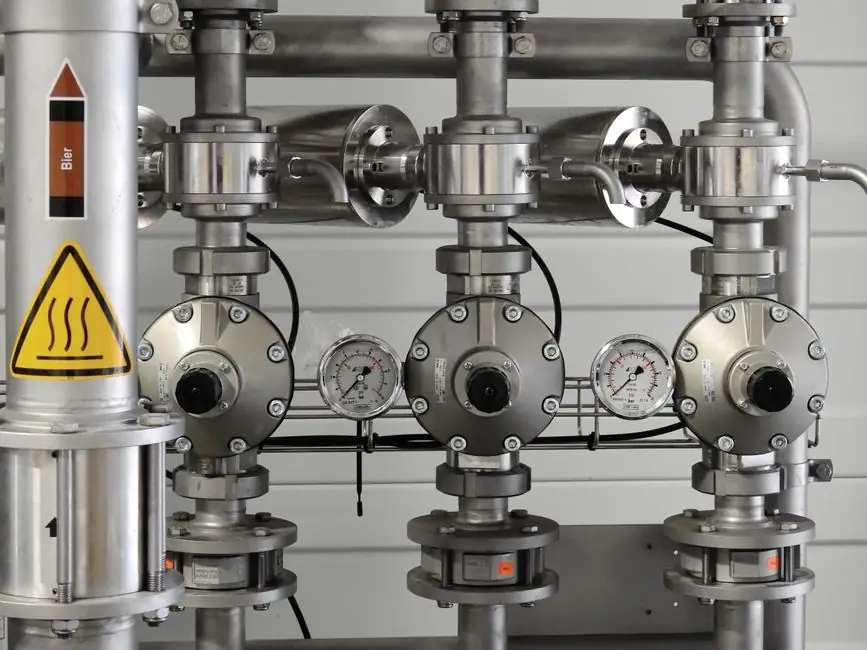
Hydraulic system manufacturing quality is enforced at five sequential gates, material selection, precision CNC machining, weld procedure qualification, surface finishing, and pressure-tested assembly, before any cylinder, valve, or manifold leaves the shop floor [S1].
The economic case for those gates is unambiguous in steel mills: unplanned hydraulic-related downtime costs $150K–$800K per hour in flat-rolled production, and contaminated fluid degrades strip thickness well before any alarm fires [S2].
Gate 1: Material Selection and Heat Treatment
Steel alloys with enhanced strength characteristics form the backbone of most hydraulic cylinders, valve bodies, and manifold blocks, and selection is driven by the operating pressure band the component will see in service [S1].
Heat treatment follows rough machining to raise surface hardness on piston rods and bearing surfaces, a step that materially extends fatigue life in 250–350 bar servo-hydraulic roll-gap circuits typical of cold rolling mills [S2]. A deviation in alloy certification or quench uniformity at this stage propagates into every downstream gate and is the single most common root cause of field weld-zone failures.
Gate 2: Machining Tolerances and Surface Finish
Modern CNC equipment holds tolerances measured in thousandths of an inch on cylinder bores and piston rods, with internal honing producing the surface roughness profile that allows dynamic seals to seat without leakage [S1].
For servo-hydraulic systems, the working tolerance is tighter still: rolling-mill roll-gap positioning requires sub-millimetre accuracy at 250–350 bar, and that resolution is only achievable when the cylinder bore roundness, piston-rod straightness, and seal-gland dimensions all sit inside their individual spec windows [S2]. Thread cutting on port connections, end caps, and mounting hardware is the leak-path most often flagged at pressure-test stands, since hydraulic fittings operate at extreme pressure and a single under-cut thread becomes a 24-hour rework.
Gate 3: Weld Procedure and Manifold Fabrication
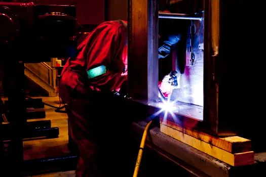
TIG and MIG welding produce the high-pressure joints in cylinder bodies, manifolds, and mounting brackets, with weld-procedure qualification records (WPQR) typically required before any production weld is accepted [S1].
Manifold fabrication concentrates the risk: a single block integrates multiple flow paths, pressure ports, and valve-mounting surfaces, so any porosity, undercut, or lack of penetration in a branch weld is a latent leak that only manifests at system proof pressure. A common shop-floor rule is to require 100% radiographic or dye-penetrant inspection on every manifold weld that sees cyclic pressure above 210 bar.
Gate 4: Surface Finishing and Plating
Hard-chrome plating on piston rods, external grinding to specified Ra values, and final honing of bores are the surface-finishing operations that determine seal life and leakage rate [S1].
The plating thickness range commonly specified is 0.025–0.050 mm with a post-grind diameter held to ±0.025 mm on rods above 50 mm, though exact values are set per component drawing rather than by a single industry default. Surface-finish defects at this gate are rarely repairable; the rod is reworked or scrapped, and a piston-rod rejection rate above 2% is a strong signal that the preceding grinding or plating cell is out of statistical control.
Gate 5: Assembly Cleanliness and Pressure Testing
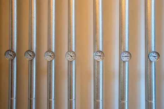
Final assembly enforces ISO 4406 fluid cleanliness on the flushing fluid, torque values on fitting connections, and a documented pressure-test sequence on every completed hydraulic system before release [S3][S5].
Technician job specs across U.S. hydraulic shops in 2026 consistently require 3–5 years of experience for hydraulic assembler roles and 4–7 years for lead-level positions, with explicit competency in interpreting schematics, setting relief valves, and verifying flow rates against spec [S3][S5]. Field evidence from steel-plant maintenance practice is direct: contaminated fluid causes servo-valve spool stiction, slow pressure response, and strip-thickness variation that shows up as a quality defect long before a hard failure [S2]. A leak-down test held to a defined pressure-decay rate over a defined dwell time is the cheapest insurance against a four-hour, $600K unplanned stop.
Process Window and Press-Side Application
Hydraulic presses apply the same quality logic to assembly, forming, straightening, and stamping operations, where the ability to hold constant force through the full stroke is what separates a hydraulic press from a mechanical press for precision work [S4].
Process parameters such as ram speed, position, pressure, and clamping force are adjusted with high accuracy so the press can be retuned between parts without re-qualification, and the data collected during the cycle supports traceability for ISO 9001 audits. For buyers evaluating press equipment against manufacturing-quality targets, the hydraulic system manufacturing equipment spec-first buyer guide maps the equipment-level criteria onto the same five-gate logic used in component production.
Selection Criteria: In-House Gate vs Contract Manufacturer

A plant deciding between in-house hydraulic-system production and contract manufacture should weigh four criteria: in-process inspection capability, weld-procedure qualification depth, cleanliness-controlled assembly space, and pressure-test stand capacity. [S1]
In-house makes sense when the plant runs 250–350 bar servo systems continuously and the cost of a 4-hour downtime event clears $600K, because the maintenance team gains direct control over the hydraulic actuator build, the flush procedure, and the ISO 4406 target. Contract manufacture fits low-volume, non-servo builds where the buyer can audit the supplier's WPQR library, leak-test records, and torque-traceability system instead of carrying fixed in-house overhead. Plants running 300-bar servo systems inside an integrated mill should review the hydraulic system production capacity planning sizing methodology before adding in-house cells, since capacity sizing drives whether the fifth gate (pressure-test stand) becomes a bottleneck.
Failure Modes and Sourcing Signals
Hydraulic manufacturing-quality failures cluster into four modes: out-of-tolerance bores that accelerate seal wear, weld porosity that leaks at proof pressure, contaminated assembly that destroys servo valves in service, and plated-rod surface defects that scratch seals within the first 100 hours [S1][S2].
Two sourcing signals reliably predict field performance: a documented leak-test pass rate above 98% on the test stand, and a first-pass yield on manifold weld inspection above 95%. Both numbers are trackable from supplier quality data, and both correlate with the unplanned-downtime exposure documented across flat-rolled steel operations. For shops that also need to size supporting components, the hydraulic cylinder bore-and-rod selection page and the broader hydraulic system reference cover the geometry, pressure-class, and material decisions that feed back into the Gate 1 material selection call.