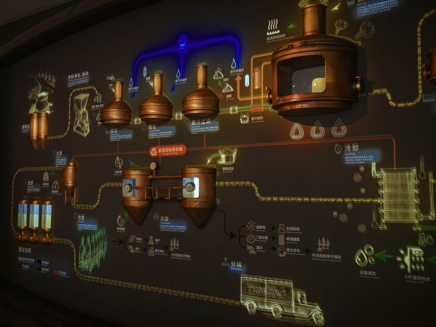
Hydrogen fuel cell (HFC) production lines combine precision-machined rotating hardware, coated membrane-electrode assemblies, and safety-monitored stack assembly into a single flow; the equipment mix a buyer specifies in 2026 reflects stack-power targets between 50–150 kW for transit and light commercial vehicles [S3].
Three equipment tiers dominate 2026 procurement: MEA coating and decal lines (slot-die, ultrasonic spray, or roll-to-roll), bipolar-plate machining and coating cells, and balance-of-plant (BOP) component manufacturing — compressors, linear guides for stack fixturing, and recirculation blowers [S2][S4].
Stack-Assembly Station: Stacking Pressure, Tolerance, and Alignment
PEM stack assembly cells operate at 0.5–4.0 MPa of pneumatic or hydraulic compression force per cell, with cell-to-cell positional accuracy held inside ±0.1 mm across a 200–400 cell stack [S4].
Stations typically integrate a vision-guided pick-and-place, a heated platen (60–90 °C for sub-gasket activation), and a force-controlled end-plate press; the crossed-roller guide is the default linear-bearing choice where stack fixturing demands 6-axis rigidity without play across a 1.5 m vertical travel. Process-engineer field checks consistently fail when the press is built on a standard ball-bearing slide: 0.05 mm of repeatability is the threshold below which contact-pressure uniformity falls off and cell-to-cell voltage spread widens by 8–15 mV under load [S4].
Membrane-Electrode Assembly (MEA) Coating Lines
MEA production divides into catalyst-coat and membrane-cast sub-lines; slot-die coating on roll-to-roll PET carriers is the workhorse for 2026 volume runs, holding wet-film tolerance within ±2 µm at line speeds of 5–15 m/min [S4].
Platinum loadings for 2026-spec automotive MEAs are specified in the 0.05–0.20 mg Pt/cm² range on the cathode, with ionomer-to-carbon ratios held at 0.6–0.9 by weight; coating booths run at 20–25 °C dew point with HEPA-filtered laminar flow to keep particle counts under ISO Class 7 (10,000 particles/m³ at ≥0.5 µm) [S4].
Drying ovens are 6–12 m convection zones with infrared preheat; line-integrated beta-gauge coating-weight measurement feeds a closed-loop trim pump at the slot-die head, holding dried catalyst areal weight within ±3% — a tighter spec than the ±5% that older 2018-vintage lines were qualified to [S4].
Bipolar-Plate (BPP) Machining and Coating Cells
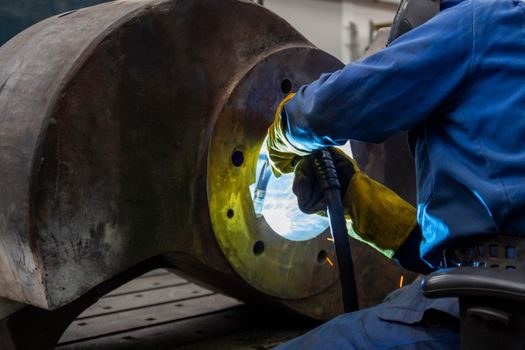
Metal BPPs dominate 2026 automotive stacks; the manufacturing cell of interest is a 5-axis CNC milling or fine-blanking cell for stainless 304L/316L foils 0.05–0.15 mm thick, followed by an anti-corrosion coating cell (amorphous carbon, Cr-C, or PVD gold) [S2].
Channel tolerances on stamped BPP lands are specified at ±0.015 mm for the active area, with a 1.0–1.5 mm channel width and 0.5–1.0 mm land width as the typical 2026 bipolar-plate geometry for 100–150 kW automotive stacks [S4].
Post-coating cells use PVD or PECVD with 0.1–2.0 µm amorphous-carbon film; per-plate contact-resistance targets fall under 10 mΩ·cm² at 1.0 MPa compaction — a metric that separates a 2026-qualified supplier from a 2020-vintage shop [S4].
Balance-of-Plant (BOP): Compressors, Sensors, and Recirculation
BOP component manufacturing is a parallel supply line feeding the stack assembly cell: centrifugal or scroll air compressors, hydrogen recirculation blowers, and coolant pumps. Precision-machined compressor shafts and impellers are specified to sub-5 µm dimensional tolerance, with IATF 16949 + ISO 14001 accreditation a hard floor for automotive Tier-1 buyers [S2].
Hydrogen-side sensors — pressure, temperature, and hydrogen-specific leak detection — must be selected with the same ATEX/IECEx zoning logic as a chemical plant; many 2026 HFC lines are now built around additive-manufacturing-material-printed sensor manifolds to consolidate fitting count.
Linear-actuated load cell test stands validate stack compression force at end-of-line; a 50 kN load cell is the default for stacks up to 400 cells, and 0.1% non-linearity is the spec floor. Suppliers that cannot demonstrate NIST-traceable calibration certificates get cut at RFQ stage [S4].
Selection Criteria: How Buyers Match Equipment to Stack-Power Class
Decision criteria for HFC manufacturing equipment selection line up against stack-power class:
• 1–10 kW (stationary/residential): MEA coating on small-format decal stations, manual or semi-automatic stack assembly, no roll-to-roll — capital under USD 5 M for a greenfield line [S4].
• 30–80 kW (light commercial, forklifts, small buses): roll-to-roll MEA coating at 5–8 m/min, automated stack assembly with vision registration, BOP components from automotive Tier-1 supply — capital USD 20–60 M for a 5,000-stack/yr line [S3][S4].
• 100–150 kW (transit bus, heavy truck): roll-to-roll MEA at 10–15 m/min, robotic stack assembly with crossed-roller guide fixturing, in-line BPP coating cells — capital USD 80–150 M for a 10,000-stack/yr line [S3][S4].
• 200 kW+ (rail, marine, stationary power): custom MEA lines with >15 m/min speeds, multi-robot stack assembly, parallel BOP test cells — capital often exceeds USD 250 M and is dominated by state-subsidized greenfield projects [S3][S4].
The bus-council membership list — BAE Systems, Ballard, Linde, and a long list of North American transit agencies — confirms that 2026 transit-bus demand is the volume driver behind most 30–80 kW class equipment orders [S3].
Safety, Atmosphere, and Zone Classification
Stack-assembly cells handling dry, un-humidified stacks can be classed non-hazardous; cells handling humidified stacks, hydrogen-purge booths, and stack test stands fall under classified zones per IEC 60079-10-1, with zone-class definitions based on hydrogen release volume and ventilation rate [S1][S4].
Safety-instrumented functions on HFC lines parallel refinery practice: redundant H₂ sniffers with 25% LEL trip, flame detectors on test stands, and emergency-purge nitrogen flow sized to dilute the largest credible H₂ release below 25% LEL inside the booth within 30 s [S1].
Open-frame stack test cells with anti-static equipment — ionization bars, dissipative flooring (1×10⁶ to 1×10⁹ Ω), and wrist-strap monitoring — are now standard at OEM test labs; non-compliance disqualifies the supplier from automotive OEM audits [S1].
2026 Failure Modes and Buyer-Side Watch-Items
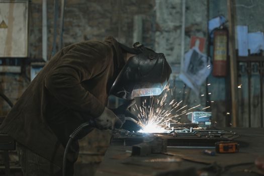
Three failure modes dominate 2026 HFC-line yield losses: MEA pinhole defects from coating-line particle events (>0.5 µm particles cause 60–80% of in-line rejects), BPP land-flatness drift beyond 0.02 mm after coating (raises contact resistance 30–50% under load), and stack compression-force creep during end-of-line cure (force drops 5–10% over 24 h if the press platen is not thermal-stabilized) [S4].
Buyers should require Cpk ≥1.33 on critical-to-quality dimensions: catalyst areal weight, BPP land flatness, and stack compression force; the literature treats Cpk <1.0 on any of these as a hard production-line-stop trigger [S4].
Suppliers without on-site optical-coordinate-measuring-machine (CMM) verification of every Nth BPP should be downgraded in the supplier scorecard; in-line laser triangulation at the press exit is the cheapest step-up for a 2026 line retrofit [S2][S4].
Trackable next nodes for HFC manufacturing equipment sourcing in 2026: IATF 16949 re-audit cycles (annual, mid-2026 cycle), the next Hydrogen Fuel Cell Bus Council board meeting on fleet-deployment targets, and the autumn 2026 slot-die coating-head OEM release windows for sub-2 µm wet-film tolerance — each is a verifiable signal a buyer can monitor without speculation [S3].
See also our earlier report, Rack-Mounted PLC Price & Cost Guide: 2026 Spec-Based Breakdown.