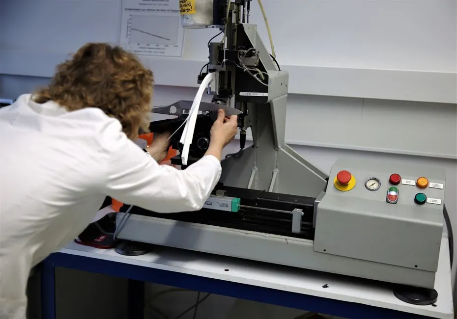
The IEC 62153-4-3 triaxial method is the most-cited test for screening effectiveness of metallic communication cables, defining surface transfer impedance (Zt) by driving a defined current on the outside of the cable shield and measuring the voltage induced on the inner conductor [S2][S8].
Zt is the ratio V/I, expressed in milliohms (or mΩ/m once normalised to length), and a lower value corresponds to a better shield; the practical fixture is a matched inner circuit (Z1 = R1) inside a conductive outer tube that is shorted at end B, producing reflections handled by a damping resistor Rdamp [S1][S5].
Scope, Frequency Range, and Sample Geometry
IEC 62153-4-3 (Edition 2.0, 2013) covers metallic communication cable test methods for surface transfer impedance using the triaxial method, classified under ICS 33.120.10 and 33.100 [S2].
Commercial labs typically run the fixture on short cable samples of 0.5-1 m (1.5-3 ft) between 100 Hz and 180 MHz; the cable-under-test (CUT) inner circuit is matched with R1 = Z1, the outer circuit has characteristic impedance Z2, and current i flows on the shield while V is measured on the inside [S1].
Below 30 MHz the LF port method (100 Hz-30 MHz) is preferred for low-impedance samples, while above 100 kHz the standard S-parameter method (extending to 180 MHz) is used; the test setup can also be modified to include connectorised cable assemblies at both ends, which makes it useful for aerospace, automotive, and military acceptance tests [S1].
Why Triaxial, and How It Differs From Other IEC 62153-4-x Methods
The triaxial test was originally designed for communications cables and is less rigorous than some alternatives but is the workhorse of the IEC 62153-4 family because it is fast, repeatable, and works on small samples [S4][S9].
Within IEC 62153, the family splits into complementary measurements: Part 4-3 is the triaxial method for Zt; Part 4-6 is the line-injection method for Zt; Part 4-7 is the tube-in-tube method; Part 4-4 covers screening attenuation above 3 GHz; Parts 4-2/4-5/4-11/4-12/4-13/4-14 use the absorbing-clamp and injection-clamp techniques for coupling or screening attenuation; Part 4-10 specifies a double-coaxial method for feed-throughs and gaskets; Part 4-9 covers coupling attenuation of balanced cables; and Part 4-0 links surface transfer impedance to recommended limits for screening attenuation [S4].
Reverb-chamber methods (IEC 62153-4-21) and semianechoic-chamber tests measure shielding effectiveness (SE) in dB by comparing shielded and unshielded power pickup, SEdB = Pu - Ps, which is directionally inverse to Zt but not a literal 1/Zt relationship, since the two metrics are measured with very different stimuli and instrumentation [S5].
Procedure: From Calibration to Zt Curve

LF port measurements (100 Hz-30 MHz) read T (output power) and R (input power) and calculate Zt directly, since these ports are designed for low-impedance devices where a standard network analyser input would lose accuracy [S1].
S-parameter measurements (100 kHz-180 MHz) record S21 on a vector network analyser, compute measured attenuation as a_meas = 10 log(P1/P2) = -20 log(S21), run a THRU calibration with test cables to get a_cal = 10 log(P1,cal/P2,cal) = -20 log(S21,cal), and then derive Zt following the IEC 62153-4-3 calculation path [S1].
Typical practical work published since 2023 (Leppäaho et al.) has reused the triaxial cell to characterise Zt responses of shielded cables under steady-state and cyclic thermal stress, random vibration, and combined environments, demonstrating that the same fixture can support reliability and qualification testing beyond a single EMC sweep [S3].
Selection Criteria: When to Use IEC 62153-4-3 vs. Alternatives
Use IEC 62153-4-3 when the deliverable is a Zt vs. frequency curve on a 0.5-1 m sample for cable or harness QC, when the band of interest sits between 100 Hz and 180 MHz, and when the test must reference the most-cited international standard for surface transfer impedance [S1][S4].
Choose a different IEC 62153-4-x method when the design problem shifts: Part 4-6 line injection for rapid production Zt checks, Part 4-7 tube-in-tube when a longer or differently shaped sample is required, Part 4-4 for screening attenuation up to and above 3 GHz, and Part 4-21 reverb-chamber when the metric must be shielding effectiveness rather than Zt [S4][S5].
For applications above 180 MHz or for full cable assemblies including connectors, labs often extend the triaxial setup (cable + connectors at both ends) and combine it with IEEE P2855, a draft Recommended Practice for characterising cable/connector assembly shielding effectiveness from DC to 40 GHz, which the working group was preparing to submit for balloting in mid-2025 [S1][S5].
Known Limitations, Error Sources, and Field Reality
The triaxial fixture has an unavoidable short-circuit termination at end B on the outer tube, which generates reflections in the outer circuit; that is why Rdamp is a defined part of the fixture rather than an optional accessory [S1].
Sample length is constrained to 0.5-1 m for a clean 50 Ω-matched measurement, and the standard's upper practical frequency is 180 MHz; pushing beyond that requires moving to Part 4-4 or Part 4-21 fixtures, which changes the calibration model entirely [S1][S4].
Comparing Zt across vendors is only valid when the test report states the exact IEC 62153-4-3 configuration (sample length, LF port vs. S-parameter, calibration method, and connectorisation), since Zt and SE are commonly conflated even though one is an impedance in mΩ and the other is a logarithmic ratio in dB [S5].
Comparison of Main Options for Cable Shielding Characterisation
On four practical decision criteria: triaxial IEC 62153-4-3 scores high on standard recognition and low sample cost (0.5-1 m, no anechoic room), but is capped near 180 MHz and limited to Zt as an impedance value; line-injection (IEC 62153-4-6) and tube-in-tube (IEC 62153-4-7) trade some standard recognition for more flexible sample geometry; screening-attenuation methods (IEC 62153-4-4 above 3 GHz) extend frequency range at the cost of larger, more complex fixtures; and reverb-chamber SE per IEC 62153-4-21 gives a dB-number practical for whole-cable assemblies, but no direct Zt value, so it is complementary rather than substitutive [S1][S4][S5].
For procurement language, specify "surface transfer impedance per IEC 62153-4-3, 0.5-1 m sample, 100 Hz-180 MHz, Zt reported in mΩ/m," and accept reverberation-chamber SE per IEC 62153-4-21 only as a supplementary metric when the cable assembly, not the bulk cable, is the deliverable [S1][S5].
Trackable signals for the next planning cycle: the IEEE P2855 working group's 2025 draft submission for cable/connector assembly shielding effectiveness from DC to 40 GHz, and any IEC 62153-4-3 maintenance amendment that may revisit the 180 MHz upper edge as S-parameter fixtures mature [S5].
Detailed specification references: measurement test 3, shielded cable, and electronic test.
Related analysis: 8 ft Dock Leveler at 12 in. Below Dock: Grade, Equipment Fit, Spec Rules.