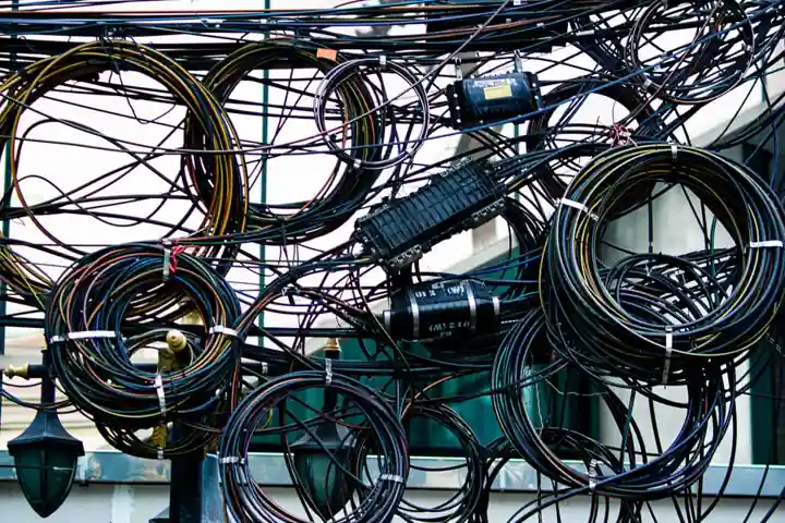
For 24 AWG shielded twisted-pair constructions in the 1/4 inch (≈6.35 mm) OD class, published catalog OD runs about 0.315 in (8.0 mm) at 4 pairs (D-200-4) and 0.387 in (9.83 mm) at 7 pairs (D-200-7) on National Wire's D-200 series, with 24 AWG conductors, 1.61 ns/ft propagation delay, and 41-61 lb/1000 ft (≈61-91 kg/km) weight [S2].
1/4 inch OD is a useful mechanical threshold, not an electrical one: it is the cutoff between "fits a 1/2 in EMT" and "must step up to 3/4 in EMT" under NEC Chapter 9, and it also defines the practical limit for mass-termination IDC connectors. The pair count, shield style (overall braid, individual pair foil, or both), jacket material, and armor all push the OD in opposite directions, which is why a 24 AWG cable from one supplier can sit at 0.30 in OD while an equivalent from another sits above 0.40 in.
What "1/4 inch gauge" actually means in catalog OD
The 1/4 in figure is shorthand for the OD band 0.220-0.280 in that lets a cable pull freely through a 1/2 in EMT after bend radius is respected, and through standard 1/4 in cable glands without exceeding the gland's clamping range [S1]. For 24 AWG twisted-pair cable, hitting that band usually means 1-2 pairs with overall foil + braid; as soon as you add a third pair or an inner jacket, OD steps out of the 1/4 in band on most constructions.
For comparison, Belden's 24 AWG multi-conductor and multi-pair electronic cable range spans AWG 28 down to 12 AWG, with overall and individual shielding options that let the same conductor gauge land anywhere from a 0.15 in (1-pair) to 0.60 in+ (multi-pair with overall braid + jacket) OD envelope [S3]. National Wire's 1-conductor through 4-conductor MIL-C-27072 shielded instrument cable at 24 AWG runs 0.097 in (conductor) → 0.155 in (2-cond twisted) → ≈0.20 in (3-cond) → ≈0.24 in (4-cond), so the 1/4 in threshold is essentially the 4-conductor 24 AWG ceiling before adding a second pair layer [S2].
Pair-count vs OD scaling on real catalog data
National Wire's D-200 series data table gives the most direct scaling rule: 4 pairs (D-200-4) at 0.315 in (8.00 mm) and 7 pairs (D-200-7) at 0.387 in (9.83 mm), both on 24 AWG with the same shield and jacket system, so each added pair adds roughly 0.024 in (0.6 mm) to the OD in that construction [S2]. Two-conductor twisted 24 AWG (NB1936N2SJ) is just 0.155 in (3.94 mm) OD; the jump from 2 conductors to 4 pairs is therefore roughly 2x, and from 4 pairs to 7 pairs another ≈23% [S2].
Shielding typically adds 15-25% to the overall diameter of an equivalent unshielded construction, per Industrial Monitor Direct's NEC conduit-fill reference, which is why two 24 AWG twisted pairs that measure 0.20 in unshielded will commonly finish at 0.23-0.25 in with overall aluminum/polyester foil + drain, and 0.30+ in with an additional tinned-copper braid (90% min coverage per MIL-C-27072) [S1][S2]. When the spec also calls for an overall thermoplastic jacket over the shield, OD climbs another 0.03-0.05 in; AWC's 14 AWG 4-conductor shielded SOOW is a useful high-gauge reference, finishing at 0.555 in OD with a 600V rating, -40°C to +90°C range, and 0.045 in nominal insulation thickness [S6].
Selection criteria: gauge, pair count, shield style, jacket

Four decision variables drive the OD of a 24 AWG shielded cable more than anything else, and they should be locked before pulling catalog data: (1) pair count (1, 2, 4, 7, 12, 25), (2) shield style (overall foil only / overall braid only / overall foil + braid / individual pair foil + overall), (3) jacket material (PVC, PE, TPE, PUR, FEP, TPE-Santoprene) and armor (none, serve, interlock), and (4) voltage/temperature rating which sets dielectric thickness [S4].
Texas Instruments' AN-916 cable selection guide adds a fifth: twisted pair is for differential (balanced) signal transport, multiconductor is for single-ended (unbalanced), and the cable you pick should match the signalling scheme, not the OD target [S4]. The same guide notes that a 2-conductor twisted cable is electrically equivalent to a single twisted pair, so if the datasheet says "2-conductor shielded" it can often serve a single differential pair, while "4-conductor" typically maps to two pairs. For process instrumentation specifically, signal runs to RTDs, thermocouples, strain gauges, and load cells almost always need individual pair shielding plus an overall shield, and the right cable selection reference walks through that decision in more detail.
Typical OD bands for 24 AWG shielded twisted-pair cable
Putting the catalog data side by side, three useful bands emerge for 24 AWG shielded twisted-pair cable: (a) 1-2 pair with overall foil only → 0.18-0.24 in OD, (b) 2-4 pair with overall foil + braid → 0.28-0.36 in OD, (c) 7-12 pair with overall foil + braid + jacket → 0.38-0.50 in OD [S2][S3]. Anything past 12 pairs at 24 AWG with a braid shield commonly crosses 0.55 in OD and is no longer a 1/4 in-class cable.
Noramco's electronic wire and cable catalog carries the same architecture in a different format, tabulating nominal diameter in inches and mm, nominal impedance in ohms, and nominal velocity of propagation side by side with pair count, which is the right way to read OD: diameter alone is meaningless without the impedance and shield effectiveness that come with it [S7]. DigiKey forum engineers building 3-conductor individually-shielded bundles for electrochemistry work landed on ≈2.75 mm OD (0.108 in) for 26 AWG individually-shielded coax cores with jacket, illustrating that going to finer gauges is the other route back into the 1/4 in band when pair count is forced up [S5].
Conduit fill, glands, and bend radius downstream effects
For a 0.315 in OD 4-pair 24 AWG cable, cross-sectional area is ≈0.078 in², so a 1/2 in EMT (0.304 in² internal at 40% = 0.122 in² usable) takes 1 such cable, while a 3/4 in EMT (0.508 in² at 40% = 0.203 in²) takes 2; a 1 in EMT takes 4.
Shielded cable is governed by the shielded cable construction rules and pulled through walls using a cable gland sized to the manufacturer's clamping range, often 0.20-0.35 in for the 1/4 in-class OD band. For instrument-signal cable runs (4-20 mA loops, Foundation Fieldbus, PROFIBUS PA), NEC Article 725 and the relevant checking and testing apparatus commissioning rules apply; for power-limited tray cable (PLTC) the same construction is permitted in trays and raceways. National Wire's MIL-C-27072 data sheet is explicit: "Recommended flex diameters should be greater than 20 cable diameters for bending at -40°C", which on a 0.315 in OD cable means a 6.3 in static bend floor and a 12.6 in flex floor [S2].
When 1/4 in OD is the wrong target
Forcing a 24 AWG shielded cable into the 1/4 in band is the wrong move when (a) the run is over 100 m and needs 25 pairs or more, (b) the spec calls for individual pair shielding plus overall braid plus interlock armor (OD will hit 0.50-0.80 in regardless of gauge), or (c) the installation is OSP/buried and needs a flooded jacket or double jacket that adds another 0.06-0.10 in [S4][S7]. In those cases, the right call is to step up the conduit size or switch to a higher-pair-count cable and accept a larger OD.
Conversely, if the application truly needs 1/4 in OD and 24 AWG is just a target, the alternative routes are: drop to 26 AWG (D-200 line drops OD by ≈0.02 in per step down), reduce pair count to 1-2, drop the braid and keep foil-only shielding, or specify a thinner-wall jacket (TPE vs standard PVC) [S2][S3]. The decision is rarely electrical, it is mechanical and code-driven, which is why the right first move is to lock the OD band, the pair count, and the shield style as three independent variables before opening a catalog.
Key numbers to put on the datasheet line

For a 24 AWG shielded twisted-pair cable aimed at the 1/4 in (0.220-0.280 in) OD band, the four numbers a buyer should require in writing are: nominal OD in inches and mm, pair count, shield construction (foil-only / braid-only / foil + braid / individual pair foil + overall), and jacket material with temperature range. The four numbers that go on the installation drawing are: minimum bend radius (static and dynamic), weight per 1000 ft or kg/km, NEC conduit-fill cross-sectional area in in², and the compatible cable gland clamping range in inches. Anything less, and the spec is incomplete. [S2]
Trackable signal for the next quarter: Belden, National Wire, and Noramco all publish OD vs pair count curves on their public catalog pages, so any spec change driven by a 2026 NEC revision, a MIL-C-27072 update, or a shift to LSZH jacket mandates will show up there first [S3][S2][S7]. For a deeper look at how gauge, pair count, and shield type trade off specifically for low-level signal runs, the shielded cable selection for load cell and strain gauge signal runs reference has worked examples against the same OD bands discussed here.