CIM (Ceramic Injection Molding) feedstocks, direct-AM ceramic molds for investment casting, and traditional refractory slumping molds now cover three distinct spec lanes, and a drawing routed into the wrong one will fail at debinding, sintering, or first-shot release.
The 2026 process envelope is clear: CIM parts run small, complex, high-purity alumina or zirconia bodies with controlled debinding and ceramic sintering [S1]; direct-AM ceramic molds and cores target investment casting of high-temperature alloys with graded porosity and reduced binder use [S2]; fused-silica and alumina-rich slumping molds remain the workhorse for kilnformed glass work where thermal cycling dominates the wear model [S3].
When a Part Belongs in CIM, and When It Does Not
CIM is the right review lane when the part needs ceramic behavior (electrical insulation, hardness, wear resistance, chemical stability, or high-temperature performance) and the geometry is small and complex enough that machining fired ceramic blanks would be cost-prohibitive [S1]. The CIM route mirrors Metal Injection Molding: feedstock preparation, injection molding, debinding, then ceramic sintering, but the final part behaves as a ceramic, not a metal [S1]. Direct substitution of a MIM part by changing material alone is the most common spec error: load path, brittleness, chipping, and finishing must all be re-validated before tooling is committed [S1].
For mold and die tooling specifically, CIM is most often evaluated for small, intricate wear inserts, insulating sleeves, and nozzle or guide features where the casting mold face carries abrasive contact but minimal impact load. Thin lips, sharp internal corners, abrupt wall changes, slender unsupported features, tight sealing faces, and threaded loading are all flagged for redesign or alternative routing before the project enters CIM feasibility review [S1].
Direct Additive Manufacturing of Ceramic Molds and Cores
Direct 3D printing of ceramic molds and cores for investment casting is consolidating around three trends: high-temperature alloy capability, more sustainable binder selection, and functional gradients, specifically graded porosity, all summarized in a June 2026 Open Ceramics review (article 100934) [S2]. The review separates direct AM from conventional IC, from AM-assisted IC using printed patterns, and from AM applied to sand casting mold tooling, so a buyer can place the technology lane before sourcing a machine or a service bureau [S2].
Process limitations remain real: material-binder compatibility restricts which refractory systems can be printed, surface quality is not yet equivalent to machined or pressed ceramic tooling, and scalability beyond prototype lot sizes is still constrained by build chamber volume and post-processing throughput [S2]. Where the application justifies it, the mold base geometry can be co-designed with a graded-porosity ceramic face to control cooling and reduce hot-tear risk in superalloy and single-crystal casting, but the trade is higher per-piece cost and a narrower supplier list [S2].
Common CIM Material Systems and What They Buy You
Alumina (Al2O3) is the default CIM body for electrical insulation and general wear; zirconia (Y-TZP, Mg-PSZ) is specified where higher fracture toughness and lower thermal conductivity are needed; silicon carbide and silicon nitride are reserved for the upper end of wear and thermal-shock duty, with cost and sinterability rising accordingly [S1]. Material choice sets the sintering temperature window, the achievable surface finish, and the finishing operations that follow (diamond grinding, lapping, or no finishing at all for as-sintered faces) [S1].
The project review should lock the material system before tooling steel is cut, because changing grade mid-project forces a new shrinkage model, a new mold base cavity, and typically a new debinding-sintering recipe. For context on adjacent ceramic spec work, the industrial ceramic selection for medical devices spec map walks the same alumina/zirconia comparison with tighter biocompatibility constraints, and the automotive ceramic selection map covers wear-grade ceramics in engine and sensor positions.
Slumping and Kiln-Form Molds: a Different Wear Model
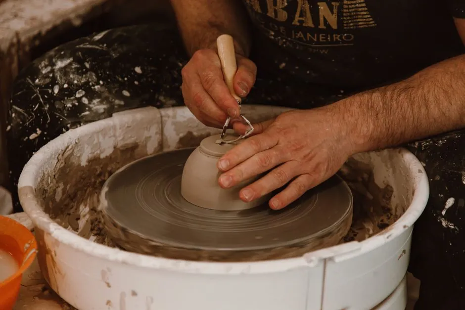
For glass slumping and kiln-forming, the ceramic mold is consumed by repeated thermal cycling rather than mechanical load, and the spec drivers are different: ability to survive hundreds of firings, clean release of the glass, and dimensional stability across the slumping temperature range [S3]. A well-made ceramic mold can last for hundreds of firings with proper care, including routine application of a kiln-wash release agent before each cycle [S3].
The non-negotiable prep step is kiln-wash or primer on every firing, because uncoated ceramic will bond glass to the mold surface and ruin both pieces; the second non-negotiable is matching the mold, glass COE, and firing schedule as a single system, not three independent choices [S3]. The mold must also fit inside the kiln with clearance for air circulation, and a single COE per project avoids coefficient-of-expansion mismatch that cracks the glass or the mold [S3].
Selection Criteria Comparison: CIM vs Direct-AM vs Slumping Molds

Lining the three routes against four decision criteria clarifies the lane: (1) CIM wins on small complex geometry and high annual volume, but loses on part size and impact loading [S1]; (2) direct AM of ceramic molds and cores wins on geometry freedom, graded porosity, and short iteration cycles for investment casting, but loses on surface finish, per-piece cost, and material-binder restrictions [S2]; (3) slumping molds win on thermal-cycling durability and low unit cost at studio scale, but are not a structural tooling solution for metal casting [S3].
The decision tree reduces to function first, then geometry, then volume: if the part is a ceramic component, CIM; if the part is a tooling consumable for investment casting a high-temperature alloy, direct AM; if the tooling shapes glass, slumping mold. Mixing lanes (for example, trying to use a slumping-grade refractory in a metal-casting die) fails on thermal conductivity, thermal-shock resistance, or release behavior, regardless of dimensional accuracy.
Design Risks and Inspection Decisions
Risk items in CIM center on geometry that survives injection but fails debinding or sintering: very long unsupported features, extremely thin lips, sharp internal corners, and wall transitions that cannot be chamfered or radiused will crack, warp, or distort during the high-temperature cycle [S1]. Inspection should be defined alongside the material choice: dimensional checks on as-sintered parts differ from machined-part metrology, and surface-finish requirements may need a lapping step that adds cost and lead time [S1].
The funding and authorship trail (DFG Walter Benjamin Fellowship, grant 538765456) is a useful signal that the review meets peer-review standards, though it does not by itself validate any service bureau's process [S2].
Where This Is Going Next

Two signals are worth tracking through late 2026: wider publication of graded-porosity AM ceramic cores in production nickel-superalloy castings, and any shift in CIM debinding chemistry that opens larger wall-thickness windows without cracking [S2]. For tooling buyers, the practical next step is to map every active mold and die drawing against the three lanes above and flag any drawing that sits in two lanes at once, since those are the projects that will burn the most engineering hours if the lane is not chosen up front.