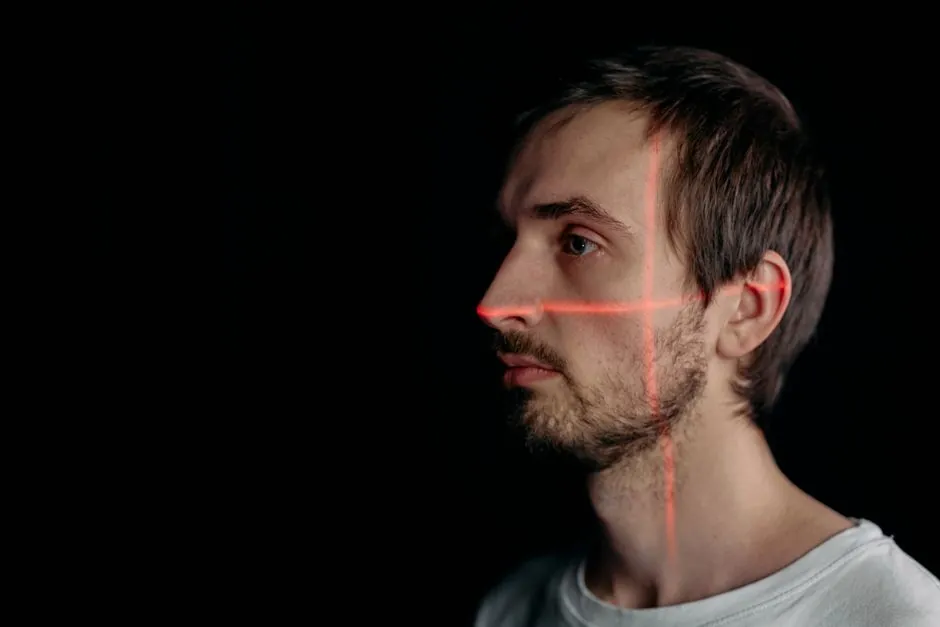
A laser distance meter (LDM) achieves commissioning-grade confidence by checking time-of-flight readings against a known baseline at short, mid, and long setpoints, with handheld units typically specified at ±2 mm accuracy over ranges up to 200 m and telescope units at roughly ±1 m over 600–3000 m [S4].
The procedure is built on the core time-of-flight formula, distance = (speed of light × time) ÷ 2, where modern LDM electronics resolve nanosecond-scale pulse intervals to deliver millimeter precision without physical contact with the target [S1][S6]. For acceptance, technicians treat the meter as a calibrated sensor, not a tape replacement, and document every reading for QA traceability.
Pre-Commissioning Reference Edge and Self-Test
Commissioning begins before the first measurement, with reference-edge selection and a power-on self-test. The reference edge (front, rear, tripod, or extension bracket) must be transformed to match the application geometry, because every LDM result is reported from that physical datum, not the internal optical bench [S4].
Handheld LDMs generally specify a -10 °C to +50 °C operating envelope, a 1/6 to 1/3 Hz pulse repetition rate, and a 12 V Ni-MH rechargeable pack; a fully charged battery is mandatory because brownout during ranging corrupts the time interval measurement and the displayed value [S4]. A healthy self-test displays a stable laser class warning, a battery icon, and a zeroed reference, and any error code at this stage blocks progression to range checks.
Baseline Validation Against a Calibrated Reference
The acceptance test compares LDM readings to a calibrated baseline at multiple setpoints, with 1 m, 5 m, 10 m, and 30 m as the conventional sweep for handheld units. Engineers commonly use a calibrated tape, an invar baseline, or a fixed architectural dimension traceable to a national metrology institute as the ground truth [S1][S2].
Accuracy expectation is set by the device class: handheld LDM ±2 mm over ranges under 200 m; telescope-class LDM ±1 m over 600–3000 m, and any reading outside these bands is a fail [S4]. Surface target selection matters, since highly reflective or transparent targets can bias the return pulse; matte white targets are the baseline reference for commissioning, with retroreflective tape reserved for long-range tests [S6].
Functional Verification of Built-In Calculations
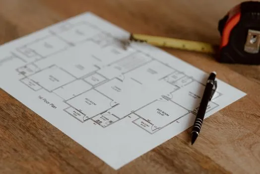
Functional checks confirm Pythagorean (indirect height), area, volume, addition, subtraction, and continuous-measurement modes against hand-calculated values. The instrument's trigonometric routines let users solve height and hypotenuse from two or three simple readings, and each routine must be checked against a known geometry during commissioning [S1][S4].
A typical indirect-height test: measure a base of exactly 3.000 m to a wall, aim at a marked point, and verify the computed height matches a steel rule within ±2 mm. Area and volume modes should be checked against a rectangular box of known dimensions, with the readout matching hand calculation to the same ±2 mm tolerance envelope. If Bluetooth or cloud data export is enabled, the data path must also be validated end-to-end before sign-off, since the meter is treated as part of a larger measurement system [S4].
Environmental and Safety Checks on Site
Site conditions can shift LDM results more than the published accuracy figure suggests, and commissioning must record ambient temperature, humidity, target distance, and surface type alongside the reading. Ultrasonic meters are far less accurate than laser units because sound waves are affected by air temperature, humidity, and nearby surfaces, and while LDMs are less sensitive, extreme thermal gradients across the beam path still bias time-of-flight by a few parts per million [S1].
Laser safety classification must be confirmed and posted at the work area, with Class 2 visible-beam units treated as eye-safe only for brief accidental exposure. For survey-grade deployments on tripods, the instrument should be re-leveled and the reference edge re-verified after any physical shock or large temperature swing, because handheld LDM specifications assume stable indoor-class conditions, not a vibrating steel platform [S4].
Documentation, Calibration Interval, and Field Use
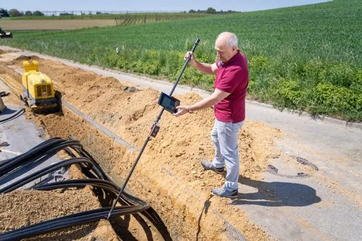
Commissioning closes with a calibration record that captures meter serial, firmware version, reference-edge selection, baseline values, observed deviations, ambient conditions, and the technician's sign-off. A well-kept record is the only evidence that a measurement chain was under statistical control when a critical dimension was reported. [S1]
Annual recheck is the practical norm, with the interval shortened for units exposed to dust, vibration, or wide thermal cycling. Acceptance criteria as simple as a ±2 mm deviation at 10 m on a stable indoor baseline catch most drift events before they propagate into fabrication errors. If a unit fails the baseline sweep, send it back for factory calibration rather than applying a field correction factor; field adjustments mask underlying timing errors and complicate future audits. For shops building a metrology stack, a paired gauge block sizing reference is a useful companion, since both rely on traceable length standards and similar environmental discipline.
Spec-level background on the components involved: laser distance meter, laser distance sensor, and tensile testing machine.