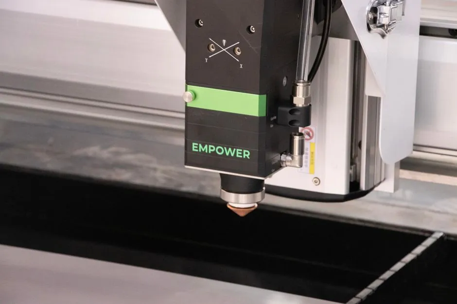
Certificate-grade traceability on a laser profile scanner line is decided at three interfaces: the per-part digital signature carrying serial number, lot, and time stamp [S1]; the calibration chain that anchors the measurement to a national standard such as AS/NZS 17025 with NATA traceability [S2]; and the machine-readable mark (Datamatrix, QR, DPM) that the same line reads back downstream [S3][S5]. If any one of the three is loose, the certificate package is loose.
This article walks through the 2026 specification and procurement view of laser profiler deployments, compares profile inspection with laser marker marks as the on-part carrier, and lays out the failure modes that pass a datasheet check but fail an auditor's check.
The traceability interface: per-part signature, not per-shift report
Process-monitoring systems built around laser profiling store a full digital signature (waveform) for every part, indexed by serial number, lot and time stamp, so that any single piece can be replayed against its master signature months later [S1]. A waveform capture stores far more datapoints than a single pass/fail bit, which is what lets an auditor reconstruct stack-up tolerances, seal presence and surface finish on a specific serial number rather than on a shift average [S1]. For a laser level or laser tracker deployment the equivalent artefact is a station-stamped log file, but the principle, one physical part = one retrievable record, is identical.
Two- or multi-point dimensional measurements are mathematically combined inside the monitor to derive slope, bore depth or surface angle, then compared to a previously stored nominal or master signature for conformance [S1]. This derived-measurement layer is the second binding point: the certificate references not just a raw reading, but a calculated dimension with a stated algorithm, and that algorithm has to be versioned in the same record set as the serial number it was applied to.
Calibration chain: AS/NZS 17025, NATA, and the warm-up reality
Laser scan micrometers used for in-process diameter, width or gap measurement on wire drawing, cable jacketing, optical fibre drawing, hot rod mills and plastic/rubber extrusion require periodic calibration to maintain measurement traceability to a national standard, and Australian practice anchors that chain to AS/NZS 17025 with NATA-accredited calibration [S2]. The Mitutoyo LSM family is a common reference: the LSM-500S resolves 0.05-10 mm diameters at 0.005 mm resolution, the LSM-516S covers up to 160 mm cylindrical workpieces, and the LSM-6902H is the ultra-high-accuracy laboratory unit, with the 16-face polygon mirror driving 3,200 scans per second on most models [S2]. These are reference values for benchmark selection; sub-micron resolution and 3,200 scans/s only count toward a certificate if the calibration certificate ties them to a named artefact on the NATA schedule.
Two pitfalls sit inside the datasheet-versus-audit gap. First, laser scan micrometers are optical instruments and the warm-up curve drifts before stabilising, so a line that records measurements inside the first minutes after power-on can produce values that fall outside the calibration uncertainty budget. Second, contact and non-contact profile inspection are not interchangeable for every surface: contact profiling is the correct choice on transparent or optically problematic surfaces, while non-contact laser profiling is the only practical option on hot, moving, soft or vibrating workpieces [S1][S2]. A certificate that lists "laser profile inspection" without naming which surface class the calibration was performed on is a risk.
Carrier mark compatibility: Datamatrix, QR, and 2D vs 3D scanning heads

The on-part carrier has to survive the same life cycle as the part it identifies. Permanent laser marking on aluminum covers raw, machined, anodized, painted and bead-blasted finishes, accepts serial numbers, part numbers, lot numbers, Datamatrix, QR codes, DPM and logos, and integrates downstream with ERP, MES and CMMS systems [S5]. For plastics and rubber, additive-free laser marking replaces inkjet, thermal transfer, labels and paint wheels, with high contrast and marking-on-the-fly for extrusion lines, and supports variable data plus machine-readable content [S4]. The 3D scanning head variant shifts the focal point along the Z axis so curved, inclined or stepped surfaces keep optimal energy density, which is exactly the geometry where 2D heads defocus and produce distorted or shallow marks [S3].
The compatibility decision is a three-way filter. (1) Surface geometry: flat parts with tight flatness tolerance are still better served by a 2D scanning head at lower cost, while 3D heads pay back only when Z-axis variation exists across the marking field [S3]. (2) Material and laser source: fiber and MOPA fiber sources integrate with 3D heads for metals and plastics, but the optical system has to be designed for the source wavelength and beam parameters, not assumed compatible [S3]. (3) Read-back ecosystem: the mark must read at the next station with the vision system already on the line, so Datamatrix density and contrast are specified together with the scanner, not after the marker is procured. The 3D-head geometry correction algorithms are what keep the Datamatrix within the read-rate budget on curved aluminum and rubber profiles [S3][S4][S5].
Selection criteria: profile inspection, scan micrometer, and marker on the same line
Three instrument categories can sit on the same certificate-bearing line, and the procurement view differs. A laser profiler is a line-of-light or point triangulation device used for cross-section, gap, seal presence and stack-up inspection, with output as a waveform signature per part [S1]. A laser scan micrometer is a beam-scanning device for diameter, width or gap on continuous production, with output as calibrated dimensional values at up to 3,200 scans/s [S2]. A laser marker is the write-side device that produces the permanent serial, lot, Datamatrix or QR carrier on the part surface [S3][S4][S5].
Decision criteria line them up directly. Measurement type: profiler captures a full cross-section signature, scan micrometer captures a single dimension at high rate, marker writes information. Calibration chain: profiler waveform is validated against a master signature [S1], scan micrometer is validated to AS/NZS 17025 / NATA [S2], marker is validated by mark contrast and Datamatrix read rate against the application. Carrier: profiler produces none, scan micrometer produces none, marker produces the on-part Datamatrix/QR [S3][S4][S5]. Best fit: profiler for assembly/seal/stack-up verification [S1], scan micrometer for diameter/width on hot, moving, soft or vibrating workpieces [S2], marker for permanent identification on metal, plastic or rubber [S3][S4][S5].
Failure modes that pass a datasheet check and fail an audit
Four patterns recur on lines that pass factory acceptance and fail a customer or regulatory audit. (1) Waveform without index: a profiler records thousands of datapoints per part, but if the serial number, lot and time stamp are not bound to that waveform, the data is a stream, not evidence [S1]. (2) Calibration certificate without application class: a NATA-traceable certificate on a scan micrometer is only valid for the surface class and warm-up state under which it was issued, and a line that runs cold or runs on a shiny transparent surface outside that class is off-certificate [S2]. (3) Beautiful mark, unreadable code: a 3D laser mark on a curved aluminum dome is visually uniform, but if the Datamatrix contrast and module size fall below the read-rate threshold for the downstream vision system, the carrier fails the audit even though the marking process was correct [S3][S5]. (4) Consumable-based marking on a "permanent" line: a line that lists laser marking in the certificate but actually runs inkjet, thermal transfer or labels for variable data loses the permanence claim, and the laser screed-style expectation of a one-process permanent record no longer holds [S4].
What an audit-ready specification actually contains
An audit-ready specification ties four items together for every instrument on the line. (1) Per-part record schema: serial number, lot, time stamp, instrument ID, algorithm version, calibration certificate ID, and the waveform or mark image, all stored in one record set [S1]. (2) Calibration scope: the named standard (e.g. AS/NZS 17025 / NATA for scan micrometers [S2]), the surface class, the warm-up condition, and the re-calibration interval. (3) Carrier specification: mark type (Datamatrix, QR, alphanumeric), contrast and read-rate thresholds, and the downstream reader model that will validate them [S3][S4][S5]. (4) Geometry handling: 2D vs 3D scanning head selection rule keyed to Z-axis variation, with the fiber/MOPA source and wavelength documented for the optics in use [S3]. Specifications built this way match the format an auditor reconstructs, not the format a salesperson quotes.
The next trackable signals to watch on 2026-08-24 are: scan-micrometer calibration intervals being shortened as warm-up drift data accumulates across continuous extrusion lines, 3D scanning head deployments expanding into aluminum and rubber curved-surface marking, and ERP/MES integration contracts that explicitly require the per-part waveform plus per-part Datamatrix to be stored in the same record set rather than as parallel logs. For cross-line sensing procurement in similar audit-heavy environments, see the Industrial Camera Certification Checklist for Structural Fabrication Job Sites for adjacent read-back audit patterns, and the Confocal Displacement Sensor Certification Checklist for Harsh Factory Floors for a non-contact displacement alternative where laser scan micrometer optics cannot read the surface.