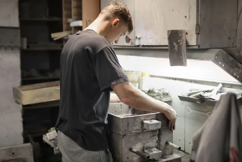
A die must fit inside the machine platen envelope, with maximum die dimensions smaller than the available platen space after accounting for clamping hardware and tie bars.
Platen size is only a geometric constraint. A sound machine selection also verifies clamping force, clamping stroke, tie-bar spacing, die-height range, and shot volume against the finished die [S1][S5].
Platen size is an envelope, not the permitted die size
The listed die-casting-machine platen dimensions include 3,314 × 3,078 × 1,066 mm and 3,315 × 2,940 × 1,120 mm, with each dimension identified as length, width, or height [S4]. These values describe the machine envelope, not automatic approval for a die measuring 1460 × 1460 mm.
A usable die must remain smaller than the platen in every relevant direction. Its exterior footprint must also clear the tie bars, guides, safety blocks, die supports, lubrication lines, and other components that occupy platen space. A published platen dimension is therefore a starting point for layout, not a die-size approval criterion.
Compare the complete die assembly against the available space, including the moving half, stationary half, mounting plates, ejector components, and any slides or inserts that extend beyond the basic die block. The machine drawing and the die layout should be reviewed as a coordinated package.
Maximum die dimensions depend on five independent constraints
The largest acceptable die is set by whichever constraint fails first: platen footprint, tie-bar spacing, die-height range, clamping stroke, or machine capacity. Passing one dimension does not clear the others [S1][S5].
The explicit comparison is simple: platen size governs physical envelope, tie-bar spacing governs installation clearance, die height governs vertical mounting, stroke governs handling and ejection, and tonnage governs pressure resistance. A machine can accommodate the geometry and still be unsuitable if its cold chamber machine cannot inject the casting or its clamp force is inadequate.
Hot chamber and cold chamber machines impose different limits
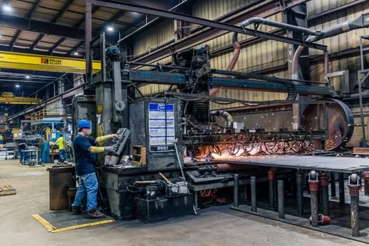
Hot-chamber machines are intended for zinc and magnesium, while cold-chamber machines are intended for aluminum and brass; aluminum melts near 660 °C and requires external ladling into a shot sleeve rather than a permanently submerged injection assembly [S5].
This alloy choice changes the machine layout and therefore the usable platen area. A zinc application commonly uses a hot chamber machine, while an aluminum application requires a cold chamber machine. Comparing only the nominal platen dimensions of these different architectures can give a false fit result.
The published comparison assigns zinc to hot-chamber equipment and aluminum to cold-chamber equipment [S5]. These operating characteristics affect tooling layout and machine choice beyond die dimensions.
For a large aluminum casting, the injection side, shot sleeve, furnace delivery, and accumulator arrangement can constrain the work envelope. For a smaller zinc casting, the same platen may provide adequate area while the die-height range, tie bars, and nozzle arrangement remain decisive.
Platen area alone does not determine machine size
Clamping force protects the die against opening under injection pressure, but maximum component size also influences the required machine capacity [S6]. A platen large enough to carry a heavy die may be paired with an injection unit that cannot fill the casting at the required pressure or rate.
The most useful comparison therefore separates fit from performance:
For a candidate machine, calculate the finished die width, height, and depth from the approved die drawing, add required clearances, and compare those values with the manufacturer’s tie-bar and platen limits. Then verify stroke, die-height range, clamp force, and shot volume separately [S1][S5].
Large castings create a capacity chain, not a single-size decision

As casting mass and projected area increase, the die grows, its closing force rises, and the molten-metal shot volume and flow demand increase.
This chain makes maximum die dimensions a poor standalone purchasing criterion. A large die may fit geometrically but exceed the machine’s useful clamping or injection capacity. Conversely, a small die may fit on a large machine, but the machine’s minimum fill or control characteristics must still support the planned shot and cycle.
The component footprint is also not necessarily the die footprint. Bosses, cores, slides, sprues, runners, and cooling channels can extend the tooling envelope. The maximum casting dimension should therefore be converted into a complete die layout before comparing it with platen geometry.
The cited process range also shows why material cannot be separated from machine selection: aluminum, magnesium, zinc, tin, lead, and copper are listed among die-cast metals [S1]. Their working temperatures, density, fluidity, and thermal effects influence machine architecture and die life [S5].
Use a die-fit checklist before ordering the machine
Platen dimensions, tie-bar spacing, and die-height range must all be available from the machine manufacturer before a tooling order is released. A published comparison lists platen size, tie-bar spacing, and die-height range as the features that determine whether proposed tooling can fit [S5].
The approval package should contain at least six checks:
Machine and tooling drawings should use the same datum. A layout showing only the die block can conceal conflicts with tie bars, side cores, large ejector systems, or guard-clearance requirements.
Machine construction adds a structural verification step

Platens are structural castings, and the cited platen specification uses JIS-FCD450 material with a stationary die-casting platen listed at 31,390 kg and 3315 × 2940 × 1120 mm [S4]. These are product-specific figures, not universal machine dimensions, but they show why platen mass, geometry, and material must be treated as a structural package.
The same material table lists JIS-FCD450 with tensile strength of 80 kgf/mm² and Brinell hardness of 260–320 HBW for that grade family [S4]. These values do not determine whether a die fits. They matter when structural suitability and machine construction are being verified alongside the tooling layout.
For operating decisions, the movable platen holds the ejector half and slides on ways, while the opposing die half is mounted on the stationary side [S7]. That arrangement reinforces the need to check total die thickness, open stroke, and ejector access rather than comparing casting dimensions with one platen face.
Cost and integration depend on rejected constraints
Choosing by platen dimensions alone can create cost without eliminating the real constraint. If tie-bar spacing blocks the die, a larger platen does not automatically solve installation. If die height exceeds the range, added bolsters consume the same envelope and can disturb parallelism. If stroke is insufficient, operating access remains compromised even when the closed die fits. [S5]
For small, high-volume zinc or magnesium parts, a hot-chamber architecture may fit the required die and cycle pattern. For larger aluminum or brass parts, a cold-chamber architecture is the relevant comparison because external shot-sleeve injection is required [S5]. Within either architecture, the same rule applies: the die must pass footprint, clearance, height, stroke, clamp-force, and shot-volume checks.
Machine selection should therefore be approved by exception, not assumption. Record each value from the OEM and each value from the released die layout, identify the controlling limit, and reject any candidate that fails even one mandatory check.
The first procurement checkpoint is a signed machine-to-die fit sheet showing platen dimensions, tie-bar spacing, die-height range, opening stroke, rated clamp force, and shot volume; if any value is blank, the proposed machine remains unverified.